prime minister and i episode 1 eng sub good drama

Metal Machining - Theory and Applications Episode 1 Part 10 ppt
Ngày tải lên :
21/07/2014, 17:20
... 1
192 Advances in mechanics
Table 6 .1 Particular values of coefficients and variables in equation (6. 41)
Case i dS
/
i
lim
1 ,i
lim
2 ,i
A
θ
,i
t
1e ,i
f cos
ψ
11 dx′ x′
1
x′
2
A
major
———
cos
η
′
c
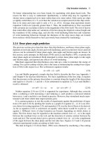
f ... chip formation. Z′
is parallel to z and z′, still in the cutting direction, but X′ is normal to, and Y′ is in, the plane
containing the cutting and chip velocities. In terms of the chip flow direction ... lim
2 ,i
t
1e ,i
A
sh
=
S ∫
A
q ,i
——— dS′
i
(6. 41)
i= l lim
1 ,i
sin f
e
A number of special cases have been introduced in Figure 6 .15 . In Figure 6 .15 (a), for
example, there are four intervals indicated...
- 20
- 306
- 0
Metal Machining - Theory and Applications Episode 1 Part 9 pptx
Ngày tải lên :
21/07/2014, 17:20
... acoustic emission. J.
Acoustic Emission 3, 10 8 11 6.
Miwa, Y., Inasaki, I. and Yonetsu, S. (19 81) In-process detection of tool failure by acoustic emission
signal. Trans JSME 47, 16 80 16 89.
Reichenbach, ... velocity discontinuity
there.
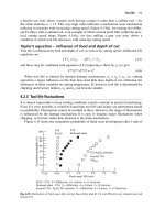
6.2.2 Machining slip-line fields and their characteristics
A major conclusion of slip-line field modelling is that specification of the rake angle a
and friction ... gives the force acting across it. Inclusion of
work hardening gives a value of 1. 77 kN (in line with experiment), while omitting it gives
3 .19 kN, in a grossly different direction.
Introducing...
- 20
- 320
- 0
Metal Machining - Theory and Applications Episode 1 Part 8 ppsx
Ngày tải lên :
21/07/2014, 17:20
... specified point can be measured,
Temperatures in machining 15 1
Fig. 5 .17 A detail of the hot junction and the associated measurement circuit
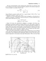
Fig. 5 .18 Calibration test results for P10 carbide and ... Eng. 10 (3), 95 10 0.
Narutaki, N. and Yamane, Y. (19 93) High-speed machining of Inconel 718 with ceramic tools.
Annals CIRP 42 (1) , 10 3 10 6.
Takeyama, H. and Murata, R. (19 63) Basic investigation ... mechanism.
Figure 4 .15 shows the cumulative probability of flank wear development after 1 min of
Tool life 13 3
Fig. 4 .15 Distributions of flank wear after turning free-cutting steel B 111 2 and difficult-to-cut...
- 20
- 358
- 0
Metal Machining - Theory and Applications Episode 1 Part 7 ppt
Ngày tải lên :
21/07/2014, 17:20
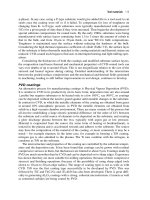
... tools and SiC whisker reinforced alumina ceramic tools when machining
steel. Carbon, silicon and nitrogen all diffuse easily in iron at elevated temperatures; and
silicon nitride and silicon carbide ... many instances in which high speed steel tools are coated with PVD TiN, TiCN
or TiAlN. Chromium nitride, boron nitride and boron carbide coatings are also under
investigation. TiN and TiC coatings ... Fatigue
Removal rate
Fig. 4.3 Tool damage mechanisms and cutting temperature
0 .1 1 10 10 0
Chipping
Micro chipping
Abrasion
Fracture
Attrition
Damage size (àm)
Fig. 4.4 Classification of mechanical...
- 20
- 407
- 0
Metal Machining - Theory and Applications Episode 1 Part 6 pdf
Ngày tải lên :
21/07/2014, 17:20
... ceramics based on alumina and silicon nitride, and the super-
hard materials polycrystalline diamond and cubic boron nitride (single crystal diamonds
are also used for the finishing of IT mirror and ... hard
and abrasive and is certainly detrimental to tool life in machining. The addition of silicon
and calcium can result in softer inclusions. It has been found that if, in addition, small
amounts ... state
temperature rise in machining. In transient conditions, heat capacity is also important
because, with conductivity, it determines thermal diffusivity k and the rate of penetration
of heat into the...
- 20
- 378
- 0

Metal Machining - Theory and Applications Episode 1 Part 5 potx
Ngày tải lên :
21/07/2014, 17:20
... characteristics in machining 83
Fig. 3 .1 Shear stress levels and work hardening severities of initially unstrained, commonly machined, aluminium,
copper, iron (b.c.c. and f.c.c.), nickel and titanium ... despite having a similar strain-hardening characteris-
tic (Appendix 4 .1 again) and an apparently higher friction interaction with the tool (as
judged by the relative sizes of its specific thrust ... as machining is concerned (with the exception of aluminium
used for mirrors and disk substrates in information technology applications), it is interest-
ing to describe how they form chips: what...
- 20
- 346
- 0
Metal Machining - Theory and Applications Episode 1 Part 4 pot
Ngày tải lên :
21/07/2014, 17:20
... turning and milling for economic production (Chapter 1) . In turn-
ing and milling practice, b ≈ 0 .15 is a reasonable approximation (actual variations with
cutting conditions are considered in more ... occur in machining
(Section 2.2), it is clear that significant temperature rises may occur in the chip. This is
without considering the additional heating due to friction between the chip and tool. ... q
f
=
tU
chip
. Of this, some fraction a* will flow into the chip and the remaining fraction (1 – a*)
will flow into the tool. The first question in considering the heating of the chip is what is
the value...
- 20
- 396
- 0

Metal Machining - Theory and Applications Episode 1 Part 3 pot
Ngày tải lên :
21/07/2014, 17:20
... realized. Instead, it is a growth in ceramic
(titanium nitride, titanium carbide and alumina) coated cutting tools that has occurred.
Figure 1. 29 shows this. It is always risky being too specific about ... hardening, despite a constant friction coefficient. Material A shows a
thicker chip still, but its friction coefficient is marginally increased too. Comparing Figures
2.8(b) and 2.7(b), changes in ... low friction coefficients
and chip equivalent strains (from equation 2.4(b)) are 0.25 to 0.5 and 1 to 3 respectively;
whereas high friction coefficients and strains are from 0.5 to 1 (and in a...
- 20
- 320
- 0
Metal Machining - Theory and Applications Episode 1 Part 2 pps
Ngày tải lên :
21/07/2014, 17:20
... evolved hand in hand with manufacturing system organization, some-
times one pushing and the other pulling, sometimes vice versa.
Manufacturing systems 15
Fig. 1. 15 A milling machine tooling magazine
Childs ... is only then, as will now be considered, that the orga-
nizational gains of cell-oriented and FMS organization bring real benefit.
1. 4.3 Milling and drilling times and costs
Equations (1. 7) and ... Introduction
Fig. 1. 14 A 5-axis milling machine with interchangeable work tables
Childs Part 1 28:3:2000 2:34 pm Page 14
In Figures 1. 16(a) and (b) the capacity of a milling machine is measured by its cross-
traverse...
- 20
- 315
- 0

Metal Machining - Theory and Applications Episode 1 Part 1 potx
Ngày tải lên :
21/07/2014, 17:20
... price of milling
machines per unit mass is similar to turning machines. All this is developed in Figure 1. 16.
12 Introduction
Fig. 1. 12 Examples of turning and milling solid, brazed and insert tools
Childs ... simulation and control of machining
processes 317
References 324
Appendices
1 Metals’ plasticity, and its finite element formulation 328
A1 .1 Yielding and flow under triaxial stresses: initial ... Page vii
1
Introduction
Machining (turning, milling, drilling) is the most widespread metal shaping process in
mechanical manufacturing industry. Worldwide investment in metal-machining machine
tools...
- 20
- 290
- 0

Gear Noise and Vibration Episode 1 Part 1 potx
Ngày tải lên :
05/08/2014, 09:20
... 18 5
11 .1
Measurement problems
18 5
11 .2
Effects
and
identification
18 7
11 .3
Simple predictions
18 9
11 .4
Possible changes
19 2
11 .5
Anti-backlash gears
19 3
11 .6
Modelling rattle
19 4
Reference
... 11 2
7 .10
Practical
problems
11 3
7 .11
Comparisons
11 7
References
11 9
8.
Recording
and
Storage
12 1
8 .1
Is
recording required?
12 1
8.2
Digital
v.
analog
12 2
8.3
Current
PC
limits
... Modulation
16 1
9.9
Pitch
effects
16 3
9 .10
Phantoms
16 5
References
16 6
10 .
Improvements
16 7
10 .1
Economics
16 7
10 .2
Improving
the
structure
16 9
10 .3 Improving
the
isolation
17 1
10 .4
...
- 20
- 287
- 1

Gear Noise and Vibration Episode 1 Part 1 ppt
Ngày tải lên :
05/08/2014, 09:20
... changing
17 8
10 .7 Damping
17 9
10 .8
Production control options
18 1
References
18 3
11 .
Lightly Loaded Gears
18 5
11 .1
Measurement problems
18 5
11 .2
Effects
and
identification
18 7
11 .3
... 16 5
References
16 6
10 .
Improvements
16 7
10 .1
Economics
16 7
10 .2
Improving
the
structure
16 9
10 .3 Improving
the
isolation
17 1
10 .4
Reducing
the
T.E.
17 4
10 .5
Permissible T.E. levels
17 5
10 .6
... 18 7
11 .3
Simple predictions
18 9
11 .4
Possible changes
19 2
11 .5
Anti-backlash gears
19 3
11 .6
Modelling rattle
19 4
Reference
200
12 .
Planetary
and
Split Drives
2 01
12 .1
Design philosophies
...
- 20
- 299
- 0

Gear Noise and Vibration Episode 1 Part 2 ppt
Ngày tải lên :
05/08/2014, 09:20
... VIBRATION
4
Sound
Radiating Panel
4
AIRBORNE
NOISE
Fig 1. 4
Vibration excitation
and
transmission path.
1. 6
T.E.
-
noise
relationship
It
is
very
difficult
for a
traditional gear engineer trained
... occur with helical teeth
or
with mist lubrication.
The
excitation
is
generally
due to a
force
varying either
in
amplitude, direction
or
position
as
indicated
in
Fig.
1. 1.
Wildhaber-Novikov
or
... parallel
axis gearing.
Inst.
Mech. Eng. Conf. Gearing
in
19 70, Sept,
pp
11 1 -12 1.
8.
Furley, A.J.D.,
Jeffries,
J.A.
and
Smith, J.D.,
'Drive
Trains
in
Printing
Machines', Inst....
- 20
- 324
- 0

Gear Noise and Vibration Episode 1 Part 2 pptx
Ngày tải lên :
05/08/2014, 09:20
... VIBRATIONS
^
Antivibration
Mounts
I
TRANSMITTED
STRUCTURE VIBRATION
4
Sound
Radiating Panel
4
AIRBORNE
NOISE
Fig 1. 4
Vibration excitation
and
transmission path.
1. 6
T.E.
-
noise
relationship
It
is
... action)
and it is the
movement
or
error
in
this direction that gives
the
vibration excitation
so we
usually
specify
this.
When
using
a 3-D
coordinate measuring machine
it is
again ... accuracy
TRANSMISSION
ERROR
i
Support
Combined
Stiffnesses
Damping
4
Internal
Dynamic Response
i
BEARING
FORCES
I
Casing Casing Casing
Masses Stiffnesses Damping
I
GEARCASE
FOOT VIBRATIONS
^
Antivibration
...
- 20
- 322
- 0

Gear Noise and Vibration Episode 1 Part 3 pptx
Ngày tải lên :
05/08/2014, 09:20
... 3
tribological
conditions which
are
most likely
to
give either very
thin
oil films
or
limited metal
to
metal contact
are the
conditions which give high
friction
and
associated vibration.
... torques
than their maximum load especially
in
automotive drives
and in
industrial
machinery
may
spend much
of
their working
day
idling. Design loading
is
typically
10 0 N / mm / mm
facewidth
... relatively
flexible in the
axial direction
at
the
bearings. This means that small forces
may
give disproportionate
vibration. This problem
is
relatively easily identified when
the
drive
...
- 20
- 341
- 0


Tìm thêm:
- hệ việt nam nhật bản và sức hấp dẫn của tiếng nhật tại việt nam
- xác định các mục tiêu của chương trình
- xác định các nguyên tắc biên soạn
- khảo sát các chuẩn giảng dạy tiếng nhật từ góc độ lí thuyết và thực tiễn
- khảo sát chương trình đào tạo của các đơn vị đào tạo tại nhật bản
- khảo sát chương trình đào tạo gắn với các giáo trình cụ thể
- xác định thời lượng học về mặt lí thuyết và thực tế
- tiến hành xây dựng chương trình đào tạo dành cho đối tượng không chuyên ngữ tại việt nam
- điều tra đối với đối tượng giảng viên và đối tượng quản lí
- điều tra với đối tượng sinh viên học tiếng nhật không chuyên ngữ1
- khảo sát thực tế giảng dạy tiếng nhật không chuyên ngữ tại việt nam
- khảo sát các chương trình đào tạo theo những bộ giáo trình tiêu biểu
- nội dung cụ thể cho từng kĩ năng ở từng cấp độ
- xác định mức độ đáp ứng về văn hoá và chuyên môn trong ct
- phát huy những thành tựu công nghệ mới nhất được áp dụng vào công tác dạy và học ngoại ngữ
- mở máy động cơ lồng sóc
- mở máy động cơ rôto dây quấn
- các đặc tính của động cơ điện không đồng bộ
- hệ số công suất cosp fi p2
- đặc tuyến hiệu suất h fi p2