fun for flyers audio cd


An english lesson fun for everyone
Ngày tải lên :
15/09/2013, 03:10
... the baby brought joy ……… Mary.
5. Write another creative Caption for the Cartoon picture.
Suggestion
1
An English Lesson - Fun for Everyone
I must write
proper
sentences.
I must take
care of ... supermarket.
4. Write another Caption for the Picture.
9
Answers to #4
1 Mother and son
•
B
•
“No, I don’t download you. I give
birth to you !”
•
of ; to /for
•
“Hours at the computer have made ... famous people
3. For each of the following words, give another
word that can replace it.
A supposed ………… B famous ………………
C commercials ……………………
4. Write another creative caption for the cartoon...
- 22
- 482
- 3


Báo cáo sinh học: " Performance evaluation of space-time-frequency spreading for MIMO OFDM-CDMA systems" ppt
Ngày tải lên :
18/06/2014, 22:20
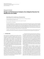
... OFDM-CDMA system block diagram.
Fig. 2. (T-F) Time-frequency mapping.
Fig. 3. Probability density function for SINR for E
s
/σ
2
=20 dB for our proposed scheme (solid) and 2D OFDM-CDMA
(dotted), for ... comparison for OFDM-CDMA system with 4Tx, 1Rx of the proposed scheme (solid) and 2D OFDM-CDMA
(dotted) in a slow fading frequency-selective environment.
Fig. 9. BER comparison for OFDM-CDMA system ... and M = 16).
Fig. 4. Probability density function for SINR for E
s
/σ
2
=20 dB for our proposed scheme with different number of
users.
8
Here, f
K
n
stands for the K
n
-th column of the (N
f
× N
f
)...
- 35
- 376
- 1

Báo cáo toán học: " Performance evaluation of space-time-frequency spreading for MIMO OFDM-CDMA systems" pptx
Ngày tải lên :
20/06/2014, 21:20
... OFDM CDMA (sim.)
2D OFDM CDMA (sim.)
Proposed OFDM CDMA (theo.)
2D OFDM CDMA (theo.)
0 5 10 15 20
25
30 35
40
45 5
0
0
2
4
6
8
10
12
14
16
18
20
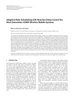
Figure 3 Probability density function for SINR for ... the results shown for SINR
pdf in Figure 3 holds for 1 receive antenna, as BER
curves for the 2D OFDM-CDMA with 4 users coincides
with our proposed system but with 8 users. Therefore,
our proposed ... Users
Proposed OFDM-CDMA
2D OFDM-CDMA
0
2
46
8
10 12 14 1
6
0
10
20
30
40
50
60
Figure 10 System throughput comparison for OFDM-CDMA system with 4Tx, 4Rx of the proposed scheme (solid) and 2D OFDM-
CDMA (dotted)...
- 13
- 411
- 0

Báo cáo hóa học: " Research Article Minimum BER Receiver Filters with Block Memory for Uplink DS-CDMA Systems" pdf
Ngày tải lên :
21/06/2014, 22:20
... 1
N = 3
MMSE DS-CDMA system
BER DS-CDMA system
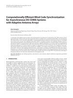
Figure 3: BER versus E
b
/N
0
performances of the MMSE DS-
CDMA system (
···◦···) and the proposed minimum BER DS-
CDMA system (
−×−)fordifferent number ... (dB)
10
−20
10
−15
10
−10
10
−5
10
0
BER
0
MMSE DS-CDMA system
BER DS-CDMA system
Figure 7: BER
0
versus NFR performances of the MMSE DS-CDMA
system (
···◦···) and the proposed minimum BER DS-CDMA
system (
−×−), when ... 11
00.20.40.60.81
MM
10
−10
10
−8
10
−6
10
−4
10
−2
10
0
BER
MMSE DS-CDMA system
DS-CDMA system
Figure 6: BER versus MM performances of the MMSE DS-CDMA
system (
···◦···) and the proposed DS-CDMA system (−×−),
when l
= 0, M =...
- 12
- 219
- 0

Báo cáo hóa học: " Research Article A Chip-Level BSOR-Based Linear GSIC Multiuser Detector for Long-Code CDMA Systems" docx
Ngày tải lên :
22/06/2014, 00:20
... receivers for cellular
CDMA,” IEEE Transactions on Vehicular Technology, vol. 49,
no. 4, pp. 1065–1085, 2000.
[3] K. Jamal and E. Dahlman, “Multi-stage serial interference can-
cellation for DS-CDMA,” ... BSOR-GSIC detec-
tor versus the relaxation factor for the case of asynchronous CDMA
multipath Rayleigh fading channel.
factor of about 1.2 for G = 2and1.4forG = 10. It is easy
to note that the proposed ... enough to converge to the decorrela-
tor’s detector average BER performance). One can notice
also that for μ
= 1.8 the average BER performance of the
proposed detector exhibits an oscillating behavior...
- 9
- 223
- 0

Báo cáo hóa học: " Research Article A Chip-Level BSOR-Based Linear GSIC Multiuser Detector for Long-Code CDMA Systems" doc
Ngày tải lên :
22/06/2014, 06:20
... receivers for cellular
CDMA,” IEEE Transactions on Vehicular Technology, vol. 49,
no. 4, pp. 1065–1085, 2000.
[3] K. Jamal and E. Dahlman, “Multi-stage serial interference can-
cellation for DS-CDMA,” ... BSOR-GSIC detec-
tor versus the relaxation factor for the case of asynchronous CDMA
multipath Rayleigh fading channel.
factor of about 1.2 for G = 2and1.4forG = 10. It is easy
to note that the proposed ... needed for convergence should be less
than K so that the computational complexity is in the order
of O (K
2
) rather than O (K
3
) for the decorrelator detector.
This is the situation for the...
- 9
- 219
- 0
Báo cáo hóa học: " Research Article Design and Performance Analysis of an Adaptive Receiver for Multicarrier DS-CDMA" doc
Ngày tải lên :
22/06/2014, 19:20
... and Performance Analysis of an Adaptive Receiver for
Multicarrier DS-CDMA
Huahui Wang, Kai Yen, Kay Wee Ang, and Yong Huat Chew
Institute for Infocomm Research (I
2
R) (A
∗
STAR), Agency for Science, ... figure repre-
sents the perfor mance of the CPIC receiver, and we can see
that the APIC outperforms the CPIC for μ
∈ (0, 0.5).
Under the same simulation settings, the BER perfor-
mances of the one- ... eight w
0
= 1andμ
1
= 0.3
Performance of CPIC, first stage
Performance of CPIC, second stage
Figure 7: BER performance of the first and second stage of the
APIC as a function of the step-size.
with...
- 10
- 436
- 0

Báo cáo hóa học: " Research Article MAP Channel-Estimation-Based PIC Receiver for Downlink MC-CDMA Systems" docx
Ngày tải lên :
22/06/2014, 19:20
... mismatch for L and τ
rms
.
SNR mismatch
The BER curves for a design SNR of 5dB, 10 dB, and 15 dB
are shown in Figure 9 with the true SNR performance. The
performance of the EM-MAP estimator for high ... considerably the perfor-
mance of PIC detector. Therefore, data and channel estima-
tion performance is obtained in the initial stage has a sig-
nificant relationship with the performance of PIC. ... likelihood functions. An EM approach pro-
posed for the general estimation from superimposed signals
[6] is applied to the channel estimation for OFDM systems
and compared with SAGE version in [7]. For...
- 9
- 177
- 0

Báo cáo hóa học: " Research Article Distortion-Free 1-Bit PWM Coding for Digital Audio Signals" pdf
Ngày tải lên :
22/06/2014, 19:20
... = 1).
cessor platform), the total number of iterations performed
for the estimation of the leading and trailing edges “jither”
values for each PCM sample must be executed before the ex-
piration ... 4163.
[2]J.Verbakel,L.vandeKerkhof,M.Maeda,andY.Inazawa,
“Super audio CD format,” in Proceedings of the 104th Conven-
tion of Audio Engineering Society (AES ’98),Amsterdam,The
Netherlands, May ... Nielsen, “Linearity and efficiency performance of switching
audio power amplifier output stages—a fundamental analy-
sis,” in Proceedings of the 105th Convention of Audio Eng ineer-
ing Society (AES...
- 12
- 378
- 0
Báo cáo hóa học: " Adaptive Rate-Scheduling with Reactive Delay Control for Next Generation CDMA Wireless Mobile Systems" pptx
Ngày tải lên :
22/06/2014, 22:20
... at the time interval
n,andT
d,i
is the mean delay target for packets of class i as
measured in frames. Therefore, the binary indicator function
I
D
[n]issetto1ifmeandelayofany class exceeds its ... takes a ran-
dom value according to a uniform distribution. It re-
tains this value for the duration of interval n. Without
any loss of generality, the four aforementioned nonstation-
ary Poisson ... arrival process Poisson, uniform range: 0 ≤ λ
1
≤ 0.4 · η
T
Class 2 arrival process Poisson, uniform range: 0 ≤ λ
2
≤ 0.3 · η
T
Class 3 arrival process Poisson, uniform range: 0 ≤ λ
3
≤ 0.38 ·...
- 15
- 435
- 0


Tìm thêm:
- hệ việt nam nhật bản và sức hấp dẫn của tiếng nhật tại việt nam
- xác định các mục tiêu của chương trình
- xác định các nguyên tắc biên soạn
- khảo sát các chuẩn giảng dạy tiếng nhật từ góc độ lí thuyết và thực tiễn
- khảo sát chương trình đào tạo của các đơn vị đào tạo tại nhật bản
- khảo sát chương trình đào tạo gắn với các giáo trình cụ thể
- xác định thời lượng học về mặt lí thuyết và thực tế
- tiến hành xây dựng chương trình đào tạo dành cho đối tượng không chuyên ngữ tại việt nam
- điều tra đối với đối tượng giảng viên và đối tượng quản lí
- điều tra với đối tượng sinh viên học tiếng nhật không chuyên ngữ1
- khảo sát thực tế giảng dạy tiếng nhật không chuyên ngữ tại việt nam
- khảo sát các chương trình đào tạo theo những bộ giáo trình tiêu biểu
- nội dung cụ thể cho từng kĩ năng ở từng cấp độ
- xác định mức độ đáp ứng về văn hoá và chuyên môn trong ct
- phát huy những thành tựu công nghệ mới nhất được áp dụng vào công tác dạy và học ngoại ngữ
- mở máy động cơ lồng sóc
- mở máy động cơ rôto dây quấn
- các đặc tính của động cơ điện không đồng bộ
- hệ số công suất cosp fi p2
- đặc tuyến hiệu suất h fi p2