electrical control circuit design software

Tài liệu Ecodial V3.38 Low-voltage electrical installation design software Fupact and variable speed drive ppt
Ngày tải lên :
12/12/2013, 13:15
... With Ecodial V3.38, design low-voltage electrical installations
the easy way
Ecodial V3.38 complies with
the latest electrical standards, bringing
LV installation design software to a
new ... project
Global electrical characteristics
Circuit default value
Display curves
Calculation result
Schneider Offer
Association guide
Ecodial V3.38
Low-voltage
electrical installation
design software
Building ... a message is displayed.
v RCD protection for final circuits supplying sockets may be present on the circuit with the socket
or on an upstream circuit. According IEC 60364 standard, Ecodial does...
- 4
- 768
- 2

Fundamentals of RF Circuit Design With Low Noise Oscillators
Ngày tải lên :
08/04/2013, 10:50
... amplifier design and includes
Load Pull measurement and design techniques and a more analytic design example
of a broadband, efficient amplifier operating from 130 to 180 MHz. The design
example ... of RF Circuit Design with Low Noise Oscillators. Jeremy Everard
Copyright © 2001 John Wiley & Sons Ltd
ISBNs: 0-471-49793-2 (Hardback); 0-470-84175-3 (Electronic)
14 Fundamentals of RF Circuit ... optimisation.
Figure 1.5
Hybrid
π
model including package components
24 Fundamentals of RF Circuit Design
()
pF66.106.12.021
=++=
T
C
(1.78)
As:
[]
()
ebsbbT
sbbeb
dB
rRrC
Rrr
f
''
''
3
2
+
++
=
π
(1.65)
then:
[]
()
2500501001066.12
501002500
12
3
+×
++
=
−
π
dB
f
=...
- 308
- 698
- 6
Allen and Holberg - CMOS Analog Circuit Design
Ngày tải lên :
18/10/2013, 12:15
... E
2
max
Allen and Holberg - CMOS Analog Circuit Design Page II.0-3
OBJECTIVE
• Provide an understanding of CMOS technology sufficient to enhance
circuit design.
• Characterize passive components ... Holberg - CMOS Analog Circuit Design II.5-6
IMPROVED LAYOUT METHODS FOR CAPACITORS
Corner clipping:
Clip
corners
Street-effect compensation:
Allen and Holberg - CMOS Analog Circuit Design Page II.1-6
Etching
Etching ... (enhancement)
Allen and Holberg - CMOS Analog Circuit Design Page I.2-1
I.1 - INTRODUCTION
GLOBAL OBJECTIVES
• Teach the analysis, modeling, simulation, and design of analog circuits
implemented in CMOS technology.
•...
- 477
- 543
- 0

Tài liệu PRINCIPLES OF ASYNCHRONOUS CIRCUIT DESIGN – A Systems Perspective pdf
Ngày tải lên :
09/12/2013, 21:15
... components. If this equivalent circuit model is speed-independent,
then the circuit is delay-insensitive.
Unfortunately the class of delay-insensitive circuits is rather small. Only
circuits composed of ... and arithmetic circuits to provide robust completion indication,
and 4-phase bundled-data with SI control at the top levels of design, i.e. some-
what different from the Amulet designs. This emphasizes ... include forks.
In chapter 6 we will explore the design of SI control circuits in great detail
(because theory and synthesis tools are well developed). As SI circuits ignore
wire delays completely some...
- 354
- 650
- 1

Tài liệu Circuit design with VHDL ppt
Ngày tải lên :
12/12/2013, 11:16
... 159
8.1 Introduction 159
8.2 Design Style #1 160
8.3 Design Style #2 (Stored Output) 168
viii Contents
TLFeBOOK
circuit, and of an ARCHITECTURE, which describes how the circuit should func-
tion. ... expected.
1.5 Design Examples
As mentioned in the preface, the book is indeed a design- oriented approach to the
task of teaching VHDL. The integration between VHDL and Digital Design is
achieved ... 1
TLFeBOOK
I CIRCUIT DESIGN
TLFeBOOK
ter, while sequential code is treated in another; data types are discussed in one chap-
ter, while operators and attributes are in another; what is at the circuit...
- 376
- 504
- 3


Ebook - Radio frequency integrated circuit design
Ngày tải lên :
09/01/2014, 02:17
... simple circuits to
minimize circuit area, but also low power dissipation to maximize battery life.
1.2 Lower Frequency Analog Design and Microwave Design
Versus Radio Frequency Integrated Circuit Design
RFIC ... xix
1 Introduction to Communications Circuits 1
1.1 Introduction 1
1.2 Lower Frequency Analog Design and Microwave
Design Versus Radio Frequency Integrated
Circuit Design 2
1.2.1 Impedance Levels ... Frequency Integrated Circuit Design
- 431
- 420
- 0

Linear circuit design handbook 2nd edition
Ngày tải lên :
09/01/2014, 16:59
... and circuits can even be produced by our foundry partners. All of the
trim circuitry tend to scale with the process features so that as the process and the amplifi er circuit shrink,
the trim circuit ... circuit shrink,
the trim circuit also shrinks proportionally. The trim circuits are considerably smaller than normal amplifi er
circuits so that they contribute minimally to die cost. The trims are ... disadvantage to this arrangement is
that the output impedance of the common emitter circuit is higher than the common collector circuit. Most of
the time this is not really an issue, since negative feedback...
- 954
- 689
- 0

Tài liệu Rf Mems Circuit Design For Wireless Communications pptx
Ngày tải lên :
19/01/2014, 20:20
... −
+×××
44 4
24 4
1
3
3
p
(2.29)
28 RF MEMS Circuit Design for Wireless Communications
2
Elements of RF Circuit Design
2.1 Introduction
The design of RF MEMS circuits for wireless applications is predicated ... thin-film microstrip lines and equivalent
distributed circuit model.
RF MEMS Circuit Design for Wireless
Communications
Wireless SystemsA Circuits Perspective 13
Transceiver
and Baseband
Phase ... devices, models, and circuits that are amenable for exploitation in
RF/microwave wireless circuit design.
This book, which assumes basic, B.S level preparation in physics or
electrical engineering,...
- 280
- 545
- 0
Tài liệu Analog Integrated Circuit Design P1 docx
Ngày tải lên :
26/01/2014, 01:20
... connected to the most negativc voltage in
a
microcircuit.
Ln
analog circuits,
this
might be the negative power supply. but in digital
circuits
it
is
normally ground or
0
V.
This
connection ...
Integrated -Circuit
Devices
and
Modelling
In this chapter, the operation and modelling of semiconductor devices are described.
Although it is possible to do simple integrated -circuit design with ... VOLTAGE REFERENCES,
AND
TRANSLINEAR CIRCUITS
Performance
of
Sample-and-Hold Circuits
334
MOS Sample-and-Hold Basics
336
Examples of CMOS
S/H
Circuits
343
Bipolar and BiCMOS Sample...
- 30
- 447
- 0
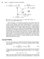
Tài liệu Analog Integrated Circuit Design P2 docx
Ngày tải lên :
26/01/2014, 01:20
... gate-source voltage.
In
most circuit applications, noncutoff
MOS-
FET
transistors are operated in strong inversion, with
Veff
>
100
mV
(many
prudent
circuit designers use a
minimum ... gate-source voltage. This
simple relationship can be quite useful during an initial circuit design.
The
second voltage-controlled current-source
in
Fig. 1.18, shown as
g,~,,
models the body effect ...
MOS
MODEWNG
In this section,
we
look at three advanced modelling concepts that a microcircuit designer
is
likely to encounter-short-channel effects, subthreshold operation, and leakage...
- 20
- 328
- 0


Process Variations and Probabilistic Integrated Circuit Design pot
Ngày tải lên :
07/03/2014, 08:20
... not only in the design of analog
circuits as already done, but also in the digital design process. The great challenge is
to assure the functionality of high complex digital circuits with respect ... conditions and does provide
the circuit developer with certain design information. For example, the designer can
determine whether the leakage current of a given cell or circuit is greater than a key
threshold ... Digital Controlled Potentiometer
DF Distribution function
DFM Design for manufacturability
DFY Design for yield
DIBL Drain-induced barrier lowering
DNL Differential Nonlinearity
DoE Design of...
- 261
- 3K
- 1
- electrical control circuit design
- tone control circuit design
- motor control circuit design software
- motor control circuit design
- control circuit design software
- control circuit design pdf
- free electrical control circuit drawing software
- electrical control circuit drawing software
- electrical control circuit design software free download
Tìm thêm:
- hệ việt nam nhật bản và sức hấp dẫn của tiếng nhật tại việt nam
- xác định các mục tiêu của chương trình
- xác định các nguyên tắc biên soạn
- khảo sát các chuẩn giảng dạy tiếng nhật từ góc độ lí thuyết và thực tiễn
- khảo sát chương trình đào tạo của các đơn vị đào tạo tại nhật bản
- khảo sát chương trình đào tạo gắn với các giáo trình cụ thể
- xác định thời lượng học về mặt lí thuyết và thực tế
- tiến hành xây dựng chương trình đào tạo dành cho đối tượng không chuyên ngữ tại việt nam
- điều tra đối với đối tượng giảng viên và đối tượng quản lí
- điều tra với đối tượng sinh viên học tiếng nhật không chuyên ngữ1
- khảo sát thực tế giảng dạy tiếng nhật không chuyên ngữ tại việt nam
- khảo sát các chương trình đào tạo theo những bộ giáo trình tiêu biểu
- nội dung cụ thể cho từng kĩ năng ở từng cấp độ
- xác định mức độ đáp ứng về văn hoá và chuyên môn trong ct
- phát huy những thành tựu công nghệ mới nhất được áp dụng vào công tác dạy và học ngoại ngữ
- mở máy động cơ lồng sóc
- mở máy động cơ rôto dây quấn
- các đặc tính của động cơ điện không đồng bộ
- hệ số công suất cosp fi p2
- đặc tuyến hiệu suất h fi p2