abb sace protection and control devices


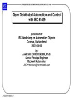
Open distributed automation and control with iec 61499.pdf
- 25
- 2.1K
- 3

Mechanisms and Mechanical Devices Sourcebook - Chapter 3
- 41
- 567
- 1
Mechanisms and Mechanical Devices Sourcebook - Chapter 4
- 33
- 507
- 0
Mechanisms and Mechanical Devices Sourcebook - Chapter 5
- 46
- 572
- 0

Mechanisms and Mechanical Devices Sourcebook - Chapter 6
- 25
- 380
- 0

Mechanisms and Mechanical Devices Sourcebook - Chapter 7
- 42
- 493
- 0

Mechanisms and Mechanical Devices Sourcebook - Chapter 8
- 52
- 642
- 0

Mechanisms and Mechanical Devices Sourcebook - Chapter 9
- 46
- 410
- 0

Mechanisms and Mechanical Devices Sourcebook - Chapter 10
- 29
- 510
- 0

Mechanisms and Mechanical Devices Sourcebook - Chapter 11
- 35
- 430
- 0
Mechanisms and Mechanical Devices Sourcebook - Chapter 13
- 33
- 561
- 1
Mechanisms and Mechanical Devices Sourcebook - Chapter 14
- 23
- 493
- 0
Mechanisms and Mechanical Devices Sourcebook - Chapter 15
- 4
- 430
- 0

Mechanisms and Mechanical Devices Sourcebook - Chapter 12
- 24
- 489
- 0
Mechanisms and Mechanical Devices Sourcebook - Chapter 16
- 36
- 364
- 0


