3 calculation of active earth pressure

The Overseas Coastal Area Development Institute of Japan pptx
Ngày tải lên :
27/06/2014, 18:20
... Improvement 33 1 7.8 Active Earth Pressure of Solidified Geotechnical Materials 33 3 7.8.1 Scope of Application .33 3 7.8.2 Active Earth Pressure .33 3 [1] Outline ... Outline 33 3 [2] Strength Parameters 33 4 [3] Calculation of Active Earth Pressure 33 4 [4] Case of Limited Area of Subsoil Improvement 33 5 7.9 Sand Compaction ... 233 Timber Piles 233 Allowable Stresses of Timber 233 6.2.1 General 233 6.2.2 Allowable Stresses of Structural Timber 233 Quality of...
- 664
- 2.2K
- 0

Báo cáo hóa học: " Design of Uniformly Most Powerful Alphabets for HDF 2-Way Relaying Employing Non-Linear Frequency Modulations" ppt
Ngày tải lên :
20/06/2014, 22:20
... The trellis of quaternary full-response CPM with modulation index κ = 1/2 Again, orthonormality of {si }3 implies i=0 bi-orthonormality of overall alphabet 10 p Figure 13 The sum of squared absolute ... by Grant Agency of the Czech Republic grant 102/09/1624; and by Grant Agency of the Czech Technical University in Prague, grant SGS 10/287/OHK3/3T/ 13 Endnotes a For the sake of notation simplicity, ... Theory 34 (2), 260–270 (1988) doi:10.1109/18.2 634 23 F Amoroso, Pulse and Spectrum Manipulation in the Minimum (Frequency) Shift Keying (MSK) Format Communications, IEEE Transactions on 24 (3) , 38 1 38 4...
- 18
- 346
- 0

Báo cáo hóa học: " Research Article Noniterative Design of 2-Channel FIR Orthogonal Filters" pptx
Ngày tải lên :
22/06/2014, 23:20
... (38 ): 3a2 + a4 , + a2 r (3) = h1 h4 = − a2 + a2 ( 43) r(1) − r (3) 10a2 + 3a4 − = + a2 (44) √ (37 ) We obtain that the maximum is achieved for a = ± For √ a = 3, we have √ √ √ √ h = √ − 3, − 3, + 3, ... using (27), the sum of the coefficients of h is a linear combination of the sum of each one of the two columns: s = h1 + ut (b + c) + hL + ut (c − b) (34 ) so we get the equation of a straight line ... Q= (38 ) Let us compare it to the other approaches The spectral method would have required a greater amount of operations; (45) √ whereas for a = − 3, we obtain √ √ √ √ h = √ + 3, + 3, − 3, −...
- 7
- 188
- 0

ARNOLD, K. (1999). Design of Gas-Handling Systems and Facilities (2nd ed.) Episode 1 Part 2 doc
Ngày tải lên :
06/08/2014, 02:20
... 0982 0982 0982 0982 130 9 130 9 130 9 130 9 1 636 1 636 1 636 1 636 1 636 1 636 1 636 1 636 1 636 19 63 39 63 19 63 19 63 9 63 39 63 19 63 39 63 19 63 19 63 2618 2618 2618 2618 2618 2618 2618 2618 Ft3 Internal Surface ... 2618 32 72 32 72 32 72 32 72 32 72 32 72 32 72 32 72 32 72 32 72 39 27 39 27 39 27 39 27 5 236 5 236 5 236 5 236 Ft2 Internal Surface Per Ft Length 236 1 2 435 , 233 0 2409 2571 2644 2702 2775 2, 838 2 932 30 16 30 89 32 25 ... 065 0295 033 3 036 0 037 3 06 03 0 731 0799 0860 1075 1269 1452 1548 130 1 1486 655 1817 1924 2 035 2181 2298 2419 1825 20 43 22 23 24 63 2679 2884 30 19 31 57 33 39 36 32 35 26 4208 4 536 48 03 51 53 54 63 5755...
- 25
- 383
- 0
ARNOLD, K. (1999). Design of Gas-Handling Systems and Facilities (2nd ed.) Episode 2 Part 1 docx
Ngày tải lên :
06/08/2014, 02:20
... Btu/SCF 1618 231 6 30 10 37 08 $3. 00/MMBtu SCF/Gallon Equivalent Value $/Gallon Equivalent Value $/Gallon 37 .5 36 .4 31 .8 27.7 0.12 13 0.1686 0.1915 0.2054 0.1820 0.2529 0.2872 0 .30 81 252 Design of GAS-HANDLING ... 200-1100 24 -30 20-50 450-600 20 -30 20-50 175 -30 0 85-160 24 -30 2-60 20-50 16-60 550-650 35 0-500 200 -30 0 70-100 14 -30 10-70 17-70 18-70 26 -30 20-70 18-70 15-70 towers packing is used instead of trays ... at 95% evaporation deg F, max -37 * 36 * 36 * -37 * ASTMD- 1 837 -81 2.5 — — 2,5 ASTMD-2 1 63- 82 2.0 2.0 — ASTM D-2 1 63- 82 — — — — ASTMD-2 158-80 ASTM D-21 58-80 ASTMD- 1 838 -84 ASTM D-2784-80I GPA Propane...
- 25
- 459
- 0

ARNOLD, K. (1999). Design of Gas-Handling Systems and Facilities (2nd ed.) Episode 2 Part 2 pps
Ngày tải lên :
06/08/2014, 02:20
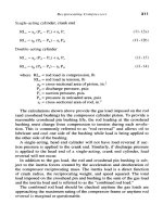
... The detailed calculation of horsepower and number of stages depends upon the choice of type of compressor, and the type of compressor depends in part upon horsepower and number of stages A first ... approximation of the number of stages can be made by assuming a maximum compressor ratio per stage of 3, 0 to 4.0 and choosing the number of stages such that: where R = ratio per stage n = number of stages ... 2.0 2.7 2,7 ! 3 440 980 3, 920 High Speed High Speed Centrifugal 100 2 2.7 2.0 2.0 2.0 2 19,602 88 190 38 0 Centrifugal Screw High Speed High Speed High Speed Screw 4.0 3. 0 3. 0 2 1 43 286 Vane Screw...
- 25
- 351
- 0

ARNOLD, K. (1999). Design of Gas-Handling Systems and Facilities (2nd ed.) Episode 2 Part 3 potx
Ngày tải lên :
06/08/2014, 02:20
... constructed of a number of pairs of rings, as shown in Figure 11-14 The gas pressure is higher on one side of each ring This compresses the rings against the sealing area Each pair of rings consists of ... maximum allowable working pressure of the cylinder determines the setting of the relief valve that is downstream of the cylinder The MAWP of the cylinder should be a minimum of 10% or 50 psi greater ... the pressure differential between the two ends of the piston Each frame is designed for a maximum number of cylinders The frame itself does not indicate the number of stages or the duty of the...
- 25
- 332
- 0
ARNOLD, K. (1999). Design of Gas-Handling Systems and Facilities (2nd ed.) Episode 2 Part 4 pdf
Ngày tải lên :
06/08/2014, 02:20
... 11 ,30 0 12,500 13, 800 12,700 13, 800 13, 800 15,000 15,000 15,000 13, 900 7,500 16 ,30 0 18,800 17,700 17,700 17,400 16 ,30 0 17,500 16 ,30 0 17,500 11,200 — 12 ,30 0 10,200 18 ,30 0 20,000 21 700 23, 300 15,000 ... 18,100 6,900 18 ,30 0 18 ,30 0 20,000 20,000 20,000 20,000 23, 300 21,700 25,000 25,000 25,000 25.000 21.700 23, 300 21,700 23, 300 20,000 16,700 20,000 16,700 Mechanical Design of Pressure Vessels ... setting of the relief valve and must be higher than the normal pressure of Mechanical Design of Pressure Vessels 32 9 the process contained in the vessel, which is called the "operating pressure" of...
- 25
- 417
- 0

ARNOLD, K. (1999). Design of Gas-Handling Systems and Facilities (2nd ed.) Episode 2 Part 5 pps
Ngày tải lên :
06/08/2014, 02:20
... SA-240 -30 4 SA-240 -31 6L SA-106-B SA-106-B SA -33 3-6 SA-105 SA-181-1 SA-1 93- B7 SA-194-2H SA-105 SA-181-1 SA-1 93- B7M SA-194-2M SA -35 0-LF1 SA -31 2 TP -30 4 SA-182 F -30 4 SA-1 93- B8 SA-194-8A SA -31 2 TP -31 6L ... SA -31 2 TP -31 6L SA-182 F -31 6L SA-1 93- B8M SA-194-8MA SA -32 0-L7 S A- 194-4 Mechanical Design of Pressure Vessels Figure 12 -3 Vessel support devices (text continued from page 33 5) The shell weight can ... Weight of shell = (11)(120)(0.8125)(20.7) = 22,200 Ib 35 3 35 4 Design of GAS-HANDLING Systems and Facilities (c) Summary: Shell Head Head Skirt Cone Misc 22,200 4,1 63 4,1 63 2,970 L656 35 ,152...
- 25
- 452
- 0

ARNOLD, K. (1999). Design of Gas-Handling Systems and Facilities (2nd ed.) Episode 2 Part 6 docx
Ngày tải lên :
06/08/2014, 02:20
... 1. 13 1.14 1.15 1.16 1.17 1.18 1.19 1.20 1.21 1.22 1. 23 1.24 1.25 1.26 1.27 1.28 1.29 1 .30 C k a 31 7 31 8 31 9 32 0 32 1 32 2 32 3 32 5 32 6 32 7 32 8 32 9 33 0 33 1 33 2 33 3 33 4 33 5 33 6 33 7 33 8 33 9 34 0 34 1 34 2 ... 1.85 18 1.87 1.88 1.89 19 C 37 3 37 4 37 5 37 6 37 6 37 7 37 8 37 9 37 9 38 0 38 1 38 2 38 2 38 3 38 4 38 4 38 5 38 6 38 6 38 7 38 8 38 9 38 9 39 0 39 1 39 1 39 2 39 3 39 3 39 4 k 1.91 1.92 1. 93 19 1.95 19 1.97 1.98 19 20 ... 34 2 34 3 34 4 34 5 34 6 34 7 1 .31 1 .32 1 .33 1 .34 1 .35 1 .36 1 .37 1 .38 1 .39 14 1.41 1.42 14 14 1.45 14 14 14 14 1.50 1.51 1.52 1. 53 1.54 1.55 1.56 1.57 1.58 1.59 16 C 34 8 34 9 35 0 35 1 35 2 35 3 35 3 35 4 35 5...
- 25
- 289
- 0

ARNOLD, K. (1999). Design of Gas-Handling Systems and Facilities (2nd ed.) Episode 2 Part 7 docx
Ngày tải lên :
06/08/2014, 02:20
... level of assurance that overpressure is going to have a very low frequency of occurrence Fire tubes can lead to fire or explosion if there is a leak of crude oil into the tubes or failure of the ... source of condition develops For example, if the pressure controller fails and the pressure increases, provide a highpressure sensor to shut-in the process If there is a leak and the pressure ... for the same pressure, the devices protecting one from overpressure will also protect the other Therefore, there may be no need for two sets of high pressure sensors The application of this procedure...
- 25
- 299
- 0
ARNOLD, K. (1999). Design of Gas-Handling Systems and Facilities (2nd ed.) Episode 2 Part 8 docx
Ngày tải lên :
06/08/2014, 02:20
... Pressure Sensor Low Pressure Sensor Pressure Pressure Safety High Pressure Safety Low Pressure Relief or Safety Valve Pressure Safety Valve Rupture Disc or Safety Head Pressure Safety Valve Pressure- ... Cover Pressure Safety Valve None Vacuum Relief Valve Pressure Safety Valve Rupture Disc or Safety Head Vacuum Pressure- Vacuum Relief Valve Vent Pressure or Vacuum Pressure Safety Element Pressure ... safety criteria In the North Sea this is often done with detailed quantified risk assessments and the calculation of an overall IRR or risk of total loss of structure Mitigation measures are incorporated...
- 25
- 252
- 0

ARNOLD, K. (1999). Design of Gas-Handling Systems and Facilities (2nd ed.) Episode 2 Part 9 ppt
Ngày tải lên :
06/08/2014, 02:20
... 2 21A 21A VA VA 2 21A 3 VA VA 21A 21A 3 VA VA 21A 21A 3 VA VA 2 1A 2{A 3 VA VA 2}A 21A 3M VA VA 2 1A 2{A 31 A VA VA 21A 21A 3yi VA VA 1}A 3 3^ VA VA VA VA 2 2}A 21A 3 314 3{ A /4 Table 15-7C Typical ... maximum allowable pressure for various steels Some common low-temperature steels include: Steel Minimum Temp, without Special Testing A -33 3 Grade ! A -33 4 Grade A -31 2TP304L A^12_TP316L - SOT - 50°F ... stress cracking Figure 7-1 shows regions of H2S concentration and total pressure where the provisions of NACE MR-01-75 govern A- 53 Grade B, A-106 Grade B, A -33 3 Grade 1, and API 5L Grades B and X-42...
- 25
- 245
- 0

ARNOLD, K. (1999). Design of Gas-Handling Systems and Facilities (2nd ed.) Episode 2 Part 10 pptx
Ngày tải lên :
06/08/2014, 02:20
... separation is not often done because of the expense of separating two chokes by a spool of pipe rated for well shut-in pressure It is much less expensive to bolt the flanges of the two chokes ... The pressure differential created by air flow through the venturi is used to regulate fuel flow to the range of 0,06 to 0.07 Ib of fuel per Ib of air Fuel Injection This is another method of supplying ... employed The principle of operation is to direct a stream of hot gases against the blading of a turbine rotor As shown in Figures 16-6 and 16-7, the gas turbine consists of 478 Design of GAS-HANDLING...
- 25
- 422
- 0

ARNOLD, K. (1999). Design of Gas-Handling Systems and Facilities (2nd ed.) Episode 2 Part 11 ppsx
Ngày tải lên :
06/08/2014, 02:20
... accumulation of significant quantities of vapor-air mixtures in concentrations above 25% of their lower flammable (explosive) limit (LFL)
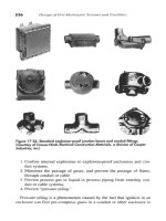
510 Design of GAS-HANDLING Systems and Facilities Figure 17- 13 ... portion of the fuel to burn without the presence of a flame This significantly reduces combustion temperature
492 Design of GAS-HANDLING Systems and Facilities Based on the results of the catalytic ... generator is out of service To minimize the size of standby equipment, some facilities have a system to automatically shed non-essential loads if one generator is out of service Some offshore facilities...
- 25
- 286
- 0

ARNOLD, K. (1999). Design of Gas-Handling Systems and Facilities (2nd ed.) Episode 2 Part 12 pps
Ngày tải lên :
06/08/2014, 02:20
... 230 215 200 180 165 160 135 120 100 J*5 842 572 536 500 446 419 39 2 35 6 32 9 32 0 275 248 212 J85 Identification Number Tl T2 T2A T2B T2C T2D T3 T3A T3B T3C T4 T4A T5 T6 Electrical Systems 5 23 ... where ignitible concentrations of gases and vapors not occur for appreciable lengths of time
Electrical Systems 533 However, the non-armored cables must satisfy IEEE 38 3 or IEEE 45 flarnmability ... toward the installation of cable systems rather than conduit systems Offshore, the vast majority of new systems are 534 Design of GAS-HANDLING Systems and Facilities Figure 17- 23 Liquidtight and flexible...
- 25
- 224
- 0
ARNOLD, K. (1999). Design of Gas-Handling Systems and Facilities (2nd ed.) Episode 2 Part 13 docx
Ngày tải lên :
06/08/2014, 02:20
... American Society of Mechanical Bearings, compressor, 296-298 Engineers (ASME), 52, 32 7, 32 8, Bernoulli's Law, 255 33 1 33 3 35 6, 39 6 Blanket gas systems, inert, 165 Amine Block valves, 37 5 -37 6, 462, 465 ... capacity, defined, 30 7 clearance, 30 5 -30 7 cooling systems, compressors, 31 2 -31 3 lubrication systems, compressors, 31 3 -31 7 s izi ng, compressors, 30 7 -31 .0 throughput capacity, 30 9 Cylinders compressors ... protection, 36 6 (ANSI), 118, 119, 248, 39 6,448, 449, Backflow, 465 532 , 547, 548 Back -pressure, 111 American Petroleum Institute, 10, Balanced-bellows relief valves, 36 3 118-119, 32 0 -32 1, 35 6, 35 7, 38 7,...
- 25
- 372
- 0

ARNOLD, K. (1999). Design of Gas-Handling Systems and Facilities (2nd ed.) Episode 2 Part 14 pot
Ngày tải lên :
06/08/2014, 02:20
... cone-bottom, 33 3, 33 5 design pressure, 32 8 -33 1 drains, 464 ellipsoidal heads, 33 2 head types, 33 1 -33 3 inspection procedures, 33 3 -33 4 low -pressure, 33 0 maximum stress values, 33 1 mechanical design, 32 7 -35 4 ... 32 7 -35 4 non-code, 32 8 564 shell and heads, 33 0 specifications, 34 0 -35 0 venting, 38 9 -39 2 wall thickness, 32 7, 33 1 -33 3 weight, 33 5 -34 0 wellhead shut-in, 118,462 working, 32 8 -32 9 Prime movers, 467-492 ... conventional, 36 0 -36 2, 37 2 critical flow, 36 7 -36 8 cylinder discharge, 279 determination, 35 6 -35 7 discharges, 37 4 -37 6 gas flow rate, 37 0 -37 1 inlet piping, 37 4 -37 5 installation, 37 4 -37 6 liquid flow rates, 37 2 -37 4...
- 9
- 297
- 0


Tìm thêm:
- hệ việt nam nhật bản và sức hấp dẫn của tiếng nhật tại việt nam
- xác định các mục tiêu của chương trình
- xác định các nguyên tắc biên soạn
- khảo sát các chuẩn giảng dạy tiếng nhật từ góc độ lí thuyết và thực tiễn
- khảo sát chương trình đào tạo của các đơn vị đào tạo tại nhật bản
- khảo sát chương trình đào tạo gắn với các giáo trình cụ thể
- xác định thời lượng học về mặt lí thuyết và thực tế
- tiến hành xây dựng chương trình đào tạo dành cho đối tượng không chuyên ngữ tại việt nam
- điều tra đối với đối tượng giảng viên và đối tượng quản lí
- điều tra với đối tượng sinh viên học tiếng nhật không chuyên ngữ1
- khảo sát thực tế giảng dạy tiếng nhật không chuyên ngữ tại việt nam
- khảo sát các chương trình đào tạo theo những bộ giáo trình tiêu biểu
- nội dung cụ thể cho từng kĩ năng ở từng cấp độ
- xác định mức độ đáp ứng về văn hoá và chuyên môn trong ct
- phát huy những thành tựu công nghệ mới nhất được áp dụng vào công tác dạy và học ngoại ngữ
- mở máy động cơ lồng sóc
- mở máy động cơ rôto dây quấn
- các đặc tính của động cơ điện không đồng bộ
- hệ số công suất cosp fi p2
- đặc tuyến hiệu suất h fi p2