Maintenance Fundamentals Episode 1 Part 1 pps

Fundamentals of Structural Analysis Episode 1 Part 3 pps
... m
5kN
1. 2 m
1m
1m
1 kN
2 m2 m
1m
1m
2 kN
2 m2 m
1m
1m
2 kN
1 kN
Truss Analysis: Force Method, Part I by S. T. Mau
49
This particular cut separates the truss into two parts. We shall use the left part ... joint.
4
F
6
F
3
F
2
3
5
4
3
4
5
1
F
3
F
1
R
y1
R
x1
3
4
5
F
4
F
2
R
y5
5
R
x5
3
5
4
10 kN
3@2m=6m
1
3
2
4
5
6
7
1
2 3
5
6
7
8
10
11
2m
9
4
Truss Analysis: Force Method,...

Fundamentals of Structural Analysis Episode 1 Part 3 pps
... joint.
4
F
6
F
3
F
2
3
5
4
3
4
5
1
F
3
F
1
R
y1
R
x1
3
4
5
F
4
F
2
R
y5
5
R
x5
3
5
4
10 kN
3@2m=6m
1
3
2
4
5
6
7
1
2 3
5
6
7
8
10
11
2m
9
4
Truss Analysis: Force Method, Part I by S. T. Mau
50
Example ... F
4
(3/5) –F
1
= 0,
F
1
= –6 kN.
2
1
2
3
6 kN
4
5
6
R
y1
R
x1
1
3
4
5
R
x5
R
y5
F
5
3
4
5
6 kN
3
F
6
3
4
5
2
F
5
F
4
F
1
3
5
4
3
4
5
Truss Analysis: Force Method, Pa...

Fundamentals of Structural Analysis Episode 1 Part 4 pps
... form:
x
y
1
2
4m
3m
3
3m
1
2
3
x
y
1
2
4m
3m
3
3m
1
2
3
x
y
1
2
4m
3m
3
3m
1
2
3
x
y
1
2
4m
3m
3
3m
1
2
3
x
y
1
2
4m
3m
3
3m
1
2
3
x
y
1
2
4m
3m
3
3m
1
2
3
1 kN
1 kN
1 kN
1 kN
1 kN
1 kN
Truss ... (
∆
T)L= 1. 2 (10
-5
)/
o
C (14
o
C) (6,000 mm)= 1mm.
(b) V
3
=1mm.
(c) V
3
= 16 kN (6 m)/[200 (10
6
) kN/m
2
(500) (10
-6
)m
2
]=0.0 01 m= 1mm.
Next we ne...
Fundamentals of Structural Analysis Episode 1 Part 5 pps
...
+
2
1
∑
=
n
i
i
1
P
∆
i
+ (1) (
∆
o
) =
2
1
j
M
j
j
vf
∑
=1
+
2
1
j
M
j
j
VF
∑
=1
+
j
M
j
j
Vf
∑
=1
(17 )
Substracting Eq. 17 by Eq. 15 and Eq. 16 yields
(1) (
∆
o
) =
j
M
j
j
Vf
∑
=1
(14 )
which ... -0. 71 -1. 00 -3.40 -4.80
6
-56.56 17 ,680 -3.20 1. 00 0.94 -3.20 -3.00
7
40.00 25,000 1. 60 -0. 71 0.33 -1. 14 0.53
8
-56.56 17 ,680 -3.20 0.00 -0.47 0.00 1. 5...
Fundamentals of Structural Analysis Episode 1 Part 7 ppsx
... Force Method, Part I by S. T. Mau
11 9
(11 ) (12 )
(13 ) (14 )
(15 ) (16 )
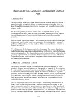
Problem 2. Frame problems.
5 m
5 m
10 kN
5 m
5 m
10 kN-m
5 m
5 m
10 kN
5 m
5 m
10 kN-m
5 m
5 m
10 kN
5 m
5 m
10 kN-m
Beam ... Beam
P
a/2EI
P
a/EI
2aaa
R
eactions
P
a/2EI
P
a/EI
11 Pa
2
/12 EI
5Pa
2
/12 EI
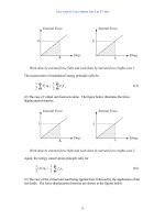
Shear(Rotation)Diagram
( Unit: Pa
2
/EI )
1
1/ 12
5 /12
1/ 6
M
oment(Deflection) Diagram
( Unit:...

Fundamentals of Structural Analysis Episode 1 Part 8 ppsx
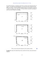
... below.
Displaced configuration.
P
2P
2P
P
1
2
2
1
1
1/ L1/L
1
1/L
1/ L
1
1
2PL
2L
1
1
2L
2L
P
Beam and Frame Analysis: Force Method, Part II by S. T. Mau
14 0
The computing is carried out using the ...
∆
d
Load
Diagram
Moment
Diagram
(M)(m)(m)(m)(m)
a~b
EI
1
(
3
1
)
(2PL)(2L)(2L)
=
EI
PL
3
8
3
00
EI
1
(
3
1
)
(2PL)(2L)(2L)
=
EI
PL
3
8
3
b~c
EI2
1
(
3
1
)
(2PL)(2L)(...

Fundamentals of Structural Analysis Episode 1 Part 9 pps
... solutions.
P
1
2
3
θ
2
’
M
1
M
1
θ
11
θ
1
’
θ
3
’
M
1
θ
21
M
1
θ
31
M
1
M
2
θ
21
M
2
θ
22
M
2
θ
32
M
3
M
3
θ
31
M
3
θ
23
M
3
θ
33
θ
2
=0
θ
1
=0
θ
3
=0
P
Beam and Frame Analysis: Force Method, Part ...
∆
2
’
+ R
1
δ
21
+ R
2
δ
22
= 0
These two equations can be put in the following matrix form.
L
L
w
L
∆
1
’
∆
2
’
L
L
w
L
R
1
δ
11
R
1
δ
21
R...
Fundamentals of Structural Analysis Episode 2 Part 1 ppsx
... M
ab
M
ba
M
bc
M
cb
M
cd
M
dc
EAM 30
DM +15 +15
COM +7.50 +7.50
DM −4.69 −2. 81
COM −2.35 1. 41
DM +0. 71 +0.70
COM +0.36 0.35
DM −0.22 −0 .14
COM −0 .11 −0.07
DM +0.04 +0.03
COM +0.02 +0.02
DM −0. 01 −0. 01
COM 0.00 0.00
SUM ... distributed loads
−2.46
4.92
-14 .27
15 .73
-7.87
I
nflection point
Beam and Frame Analysis: Displacement Method, Part I by S. T. Mau
17 9
M
bc
=
2
1...

Dimensioning and Tolerancing Handbook Episode 1 Part 6 ppsx
... condition is ∅.5 01 + ∅.005 = ∅.506. The hole has an MMC size limit of ∅. 511 and a positional
tolerance of ∅.005 at MMC. Since it’s an internal feature of size, its virtual condition is ∅. 511 − ∅.005 ... example, ∅.625 LC5 or 30 f7.
5-50 Chapter Five
Eliminate unnecessary trailing zeros.
25 .1 not 25 .10
12 not 12 .0
with not with
The exceptions are limit dimensions and bilateral (p...

Dimensioning and Tolerancing Handbook Episode 1 Part 3 ppsx
... subcommittees, including Y14 Main
Committee, Y14.3 Multiview and Sectional View Drawings, Y14.5 Dimensioning and Tolerancing, Y14 .11
Molded Part Drawings, Y14.35 Drawing Revisions, Y14.36 Surface Texture, ... Displacement from MMC
Allowable Position
Tolerance
2.74 0.00 0 .14
2.76 0.02 0 .16
2.78 0.04 0 .18
2.80 0.06 0.20
2.82 0.08 0.22
2.84 0 .10 0.24
2.86 0 .12 0.26
Tolerancing Optimi...
Từ khóa:
- thiết kế bài giảng lịch sử 8 tập 1 part 3 ppsx
- cụm di tích chiến thắng bạch đằng ở yên giang – quảng ninh part 1 ppsx
- bài giảng ứng dụng tin học trong xây dựng part 1 ppsx
- bài tập tin học đại cương part 1 ppsx
- luận văn đánh giá khả năng bắt aflatoxin g1 của cột sắc kí ái lực miễn dịch do viện pasteur tp hcm sản xuất part 1 ppsx
- bài giảng lý thuyết điều khiển tự động mô hình toán học hệ thống điều khiển liên tục part 1 pps
- giáo trình công nghệ chế biến thủy hải sản part 1 ppsx
- thiết kế bài giảng sinh học 11 nâng cao tập 1 part 6 pps
- thiết kế bài giảng toán 3 tập 1 part 10 pps
- rl stine the haunting hour episode 1
- andrew marr history of modern britain episode 1 watch online
- rl stine the haunting hour season 3 episode 1
- the moaning of life karl pilkington episode 1
- khám phản xạ dinh dưỡng cơ vòng kỳ 1 ppsx
- phần 2 máy biến áp chương 1 ppsx
- Nghiên cứu sự biến đổi một số cytokin ở bệnh nhân xơ cứng bì hệ thống
- Nghiên cứu sự hình thành lớp bảo vệ và khả năng chống ăn mòn của thép bền thời tiết trong điều kiện khí hậu nhiệt đới việt nam
- Nghiên cứu tổ hợp chất chỉ điểm sinh học vWF, VCAM 1, MCP 1, d dimer trong chẩn đoán và tiên lượng nhồi máu não cấp
- Một số giải pháp nâng cao chất lượng streaming thích ứng video trên nền giao thức HTTP
- Nghiên cứu tổ chức chạy tàu hàng cố định theo thời gian trên đường sắt việt nam
- Biện pháp quản lý hoạt động dạy hát xoan trong trường trung học cơ sở huyện lâm thao, phú thọ
- Giáo án Sinh học 11 bài 13: Thực hành phát hiện diệp lục và carôtenôit
- Giáo án Sinh học 11 bài 13: Thực hành phát hiện diệp lục và carôtenôit
- ĐỒ ÁN NGHIÊN CỨU CÔNG NGHỆ KẾT NỐI VÔ TUYẾN CỰ LY XA, CÔNG SUẤT THẤP LPWAN
- ĐỒ ÁN NGHIÊN CỨU CÔNG NGHỆ KẾT NỐI VÔ TUYẾN CỰ LY XA, CÔNG SUẤT THẤP LPWAN
- Phát triển du lịch bền vững trên cơ sở bảo vệ môi trường tự nhiên vịnh hạ long
- Phát hiện xâm nhập dựa trên thuật toán k means
- Thơ nôm tứ tuyệt trào phúng hồ xuân hương
- Chuong 2 nhận dạng rui ro
- Tranh tụng tại phiên tòa hình sự sơ thẩm theo pháp luật tố tụng hình sự Việt Nam từ thực tiễn xét xử của các Tòa án quân sự Quân khu (Luận văn thạc sĩ)
- Giáo án Sinh học 11 bài 15: Tiêu hóa ở động vật
- chuong 1 tong quan quan tri rui ro
- Nguyên tắc phân hóa trách nhiệm hình sự đối với người dưới 18 tuổi phạm tội trong pháp luật hình sự Việt Nam (Luận văn thạc sĩ)
- Giáo án Sinh học 11 bài 14: Thực hành phát hiện hô hấp ở thực vật
- Giáo án Sinh học 11 bài 14: Thực hành phát hiện hô hấp ở thực vật