Mechatronic Systems, Simulation, Modeling and Control Part 7 ppt

Mechatronic Systems, Simulation, Modeling and Control Part 7 ppt
... 2007a; Hall & Romano 2007b).
Mechatronic Systems, Simulation, Modelling and Control1 86
Mechatronic Systems, Simulation, Modelling and Control1 82
where
1
,
K
diag k k
and ...
Eikenberry, 2006; Romano & Hall, 2006; Hall & Romano, 2007a; Hall & Romano 2007b).
Mechatronic Systems, Simulation, Modelling and Control1 84
5.2 Experiment 2 − influence of a w...

Mechatronic Systems, Simulation, Modeling and Control Part 4 pptx
... Mechatronic Systems, Simulation, Modelling and Control1 40
0e k e k w h e r e
(62)
Deriving (60) and supposing that
and
are constant, ...
Mechatronic Systems, Simulation, Modelling and Control1 32
െ and in our case DOF = number of actuated joints), ࡽ...
Mechatronic Systems, Simulation, Modeling and Control Part 10 ppt
... rate, and the cumulative MTBF as software reliability assessment measures,
and the predicted relative error.
Mechatronic Systems, Simulation, Modelling and Control2 36
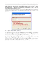
output variable, and ... Integrated Environment for Simulation
and Real-Time Control Experiment, SICE-ICASE International Joint Conference 2006
Mechatronic Systems, Simulation, Modelling and Control2 50
More...
Mechatronic Systems, Simulation, Modeling and Control Part 1 potx
... impedance, output impedance, input
1
I
Mechatronic Systems, Simulation,
Modelling and Control
Mechatronic Systems, Simulation, Modelling and Control8
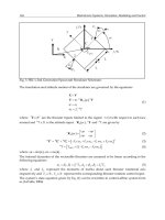
From ( 27) , the resonant frequencies can be ... designed by Dino Smrekar
Mechatronic Systems, Simulation, Modelling and Control,
Edited by Annalisa Milella, Donato Di Paola and Grazia Cicirelli
p. cm.
ISBN 978 -953-...
Mechatronic Systems, Simulation, Modeling and Control Part 3 potx
... voltage: 20
V
p-p
Mechatronic Systems, Simulation, Modelling and Control1 18
development of control strategies. By means of obtaining the dynamic model, a nonlinear
feed forward and a PD control is ... the
b
otenis
e
robot
d
esi
g
n
o
t and
a
s also
visual
m
end-
c
tive in
n
ed by
e
tween
i
stance
Mechatronic Systems, Simulation, Modelling and Control1 24
2 2 2...

Mechatronic Systems, Simulation, Modeling and Control Part 5 pot
... evolution of angle ε (—) and reference output ε
M
(· · · ).
Fig. 10. Time evolution of angle φ (—) and reference output φ
M
(· · · ).
Mechatronic Systems, Simulation, Modelling and Control1 48
2. System ... (—) and reference output φ
M
(· · · ).
Fig. 7. Time evolution of the estimated parameters
ˆ
p
1
and
ˆ
p
2
. The dotted lines represent the limited
values of variation.
Mechatron...

Mechatronic Systems, Simulation, Modeling and Control Part 8 doc
... minimal control actuator configuration of the 3-DoF spacecraft
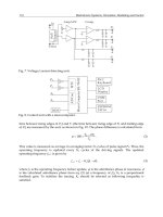
simulator. Fig. 4 reports a block diagram representation of the control system.
Mechatronic Systems, Simulation, Modelling and Control2 04
... minimal control actuator configuration of the 3-DoF spacecraft
simulator. Fig. 4 reports a block diagram representation of the control system.
Mechatronic Systems, Simulati...
Mechatronic Systems, Simulation, Modeling and Control Part 12 doc
... Mechatronic Systems, Simulation, Modelling and Control2 86
Fig. 2. General approach for modelling and testing active flexible micromechanisms
2.2 Design optimization
Modeling, ... Mecha-
tronic Systems. In: 17th International Conference on Engineering Design (ICED`09),
August 24- 27, 2009, Stanford, CA, USA, 2009
Mechatronic Systems, Simulation, Modelling and Control2 84
Fig....
Mechatronic Systems, Simulation, Modeling and Control 2012 Part 7 docx
... minimal control actuator configuration of the 3-DoF spacecraft
simulator. Fig. 4 reports a block diagram representation of the control system.
Mechatronic Systems, Simulation, Modelling and Control1 94
... for each
0,t T
for every proper control set U (Bullo &
Mechatronic Systems, Simulation, Modelling and Control2 02
Fig. 4. Block Diagram of the Control System of t...
Mechatronic Systems, Simulation, Modeling and Control 2012 Part 2 pdf
... Object
K
C
C
C
Mechatronic Systems, Simulation, Modelling and Control2 6
2 2
2
6 7 6 5 6 5 6 7
2 2
2 2 2 2 2 2
6 7 6 5 6 5 6 7
6 7 6 5 6 5 6 7
2 2 4 .
6 7 6 5 6 5 6 7
...
GeneticAlgorithm–BasedOptimalPWMinHighPower
SynchronousMachines and RegulationofObservedModulationError 27
2 2
2
6 7...
Từ khóa:
- modeling and control of wheeled mobile robots
- thiết kế bài giảng vật lý 10 tập 1 part 7 ppt
- ad hoc wireless networks architectures and protocols chapter 7 ppt
- mechanical systems design handbook modeling measurement and control
- estimation and control of stochastic systems
- recursive estimation and control for stochastic systems
- Báo cáo quy trình mua hàng CT CP Công Nghệ NPV
- chuyên đề điện xoay chiều theo dạng
- Nghiên cứu sự hình thành lớp bảo vệ và khả năng chống ăn mòn của thép bền thời tiết trong điều kiện khí hậu nhiệt đới việt nam
- Nghiên cứu tổ hợp chất chỉ điểm sinh học vWF, VCAM 1, MCP 1, d dimer trong chẩn đoán và tiên lượng nhồi máu não cấp
- Biện pháp quản lý hoạt động dạy hát xoan trong trường trung học cơ sở huyện lâm thao, phú thọ
- ĐỒ ÁN NGHIÊN CỨU CÔNG NGHỆ KẾT NỐI VÔ TUYẾN CỰ LY XA, CÔNG SUẤT THẤP LPWAN
- ĐỒ ÁN NGHIÊN CỨU CÔNG NGHỆ KẾT NỐI VÔ TUYẾN CỰ LY XA, CÔNG SUẤT THẤP LPWAN
- NGHIÊN CỨU CÔNG NGHỆ KẾT NỐI VÔ TUYẾN CỰ LY XA, CÔNG SUẤT THẤP LPWAN SLIDE
- Quản lý hoạt động học tập của học sinh theo hướng phát triển kỹ năng học tập hợp tác tại các trường phổ thông dân tộc bán trú huyện ba chẽ, tỉnh quảng ninh
- Trả hồ sơ điều tra bổ sung đối với các tội xâm phạm sở hữu có tính chất chiếm đoạt theo pháp luật Tố tụng hình sự Việt Nam từ thực tiễn thành phố Hồ Chí Minh (Luận văn thạc sĩ)
- Nghiên cứu, xây dựng phần mềm smartscan và ứng dụng trong bảo vệ mạng máy tính chuyên dùng
- Thơ nôm tứ tuyệt trào phúng hồ xuân hương
- Chuong 2 nhận dạng rui ro
- Tổ chức và hoạt động của Phòng Tư pháp từ thực tiễn tỉnh Phú Thọ (Luận văn thạc sĩ)
- Quản lý nợ xấu tại Agribank chi nhánh huyện Phù Yên, tỉnh Sơn La (Luận văn thạc sĩ)
- BT Tieng anh 6 UNIT 2
- Tăng trưởng tín dụng hộ sản xuất nông nghiệp tại Ngân hàng Nông nghiệp và Phát triển nông thôn Việt Nam chi nhánh tỉnh Bắc Giang (Luận văn thạc sĩ)
- Tranh tụng tại phiên tòa hình sự sơ thẩm theo pháp luật tố tụng hình sự Việt Nam từ thực tiễn xét xử của các Tòa án quân sự Quân khu (Luận văn thạc sĩ)
- Giáo án Sinh học 11 bài 14: Thực hành phát hiện hô hấp ở thực vật
- Giáo án Sinh học 11 bài 14: Thực hành phát hiện hô hấp ở thực vật