timer counter control register bit addressable

Timer   counter   interrupt

Timer counter interrupt

Ngày tải lên : 05/09/2013, 21:46
... định thời 13 bit Chế độ định thời 16 bit Chế độ tự động nạp lại 8 -bit Chế độ định thời chia xẻ Thanh ghi TCON – Timer/ Counter Control Register TCON D7 D6 TF1 D5 TF0 TR1 Cờ ngắt Timer1 D4 D3 IE1 ... Enable Register EA - ET2 ES ET1 EX1 ET0 EX0 • Bước 1: Chọn chế độ hoạt động timer phần lập trình cho timer • Bước 2: Cho phép ngắt: – Cho phép ngắt timer ET0 = 1; // Nếu sử dụng ngắt timer ET1 ... timer – Cho phép ng t toàn c c EA = 1; // Bắt buộc phải có sử dụng ngắt • Bước 3: Viết chương trình phục vụ ngắt Timer Chương trình phục vụ ngắt timer đặt vector ngắt 000Bh (Timer 0) 001Bh (Timer...
  • 27
  • 500
  • 5
Tài liệu Chương 3: Khảo sát timer-counter của vi điều khiển doc

Tài liệu Chương 3: Khảo sát timer-counter của vi điều khiển doc

Ngày tải lên : 22/12/2013, 06:15
... khác Timer Timer M1 0 M0 Kiểu 1 Chức Mode Timer 13 bit (mode 8048) Mode Timer 16 bit Mode tự động nạp bit Mode tách Timer : Timer0 : tách làm timer bit gồm có: Timer bit TL0 điều khiển bit mode Timer0 ... M1 M0 1 0 0 Bit chọn mode Timer Bit chọn mode Timer Nếu GATE = Timer làm việc INT1= Bit lựa chọn counter hay timer: giống Bit chọn mode Timer Bit chọn mode Timer Hai bit M0 M1 tạo trạng thái tương ... Timer0 Timer bit TH0 điều khiển bit mode Timer1 Timer1 : không hoạt động mode THANH GHI ĐIỀU KHIỂN TIMER/ COUNTER: III Thanh ghi điều khiển tcon chứa bit trạng thái bit điều khiển cho Timer0 Timer1 ...
  • 12
  • 942
  • 12
Tài liệu Timer / Counter docx

Tài liệu Timer / Counter docx

Ngày tải lên : 23/12/2013, 03:15
... Select bit Bit TMR2ON Timer2 On bit TMR2ON = bật Timer2 TMR2ON = tắt Timer2 Bit 1,0 T2CKPS1:T2CKPS0 Timer2 Clock Prescaler Select bit 00 tỉ số 1:1 01 tỉ số 1:4 1x tỉ số 1:16 Timer2 Timer CCS Timer0 ... Select bit Các bit cho phép thiết lập tỉ số chia tần số Prescaler Timer TIMER1 • Timer1 định thời 16 bit, giá trị Timer1 lưu hai ghi( TMR1H:TMR1L) • Cờ ngắt Timer1 bit TMR1IF (PIR1) Bit điều ... động cạnh lên) Timer1 Thanh ghi T1CON Bit 5,4 T1CKPS1:T1CKPS0 Timer1 Input Clock Prescaler Select bit( 1:8, 1:4 1:2, 1:1) Bit T1OSCEN Timer1 Oscillator Enable Control bit Bit Timer1 External...
  • 28
  • 662
  • 4
s7 200 timer counter

s7 200 timer counter

Ngày tải lên : 01/01/2014, 21:24
... với Timer Thành thạo lập trình với Counter Thành h Thà h thạo ngôn ngữ lậ trình ô ữ lập ì h Thành thạo cách viết chương trình Ứng dụng Timer Counter cho số toán thực tế tế Làm tiền đề cho TIMER ... S7-200 CPU 224 có 256 Timer gồm loại sau: TON: Bộ tạo thời gian trễ nhớ (On DelayTimer) TONR:Bộ tạo thời gian trễ có nhớ (Retentive On DelayTimer) ộ g ( y ) TOF: (Of Delay Timer) BỘ TRỄ THỜI GIAN ... độ tam giác g đóng K1 &K3 KHỞI ĐỘNG SAO/TAM GIÁC GIỚI THIỆU VỀ COUNTER Ứng dụng: Đếm sườn xung tín hiệu đầu vào vào S7-200 có 256 counter: C0 đến C255 Phân loại: CTU, CTD, CTUD, HSC , , , CTU:...
  • 20
  • 1.3K
  • 21
sử dụng timer counter

sử dụng timer counter

Ngày tải lên : 06/07/2014, 09:01
... Function I/O Register) Bit – PSR10: Prescaler Reset Timer/ Counter1 and Timer/ Counter0 Khi bit ghi lên 1, đếm gộp T/C1 T/C0 reset Bit bị xóa sau trình thực hoàn thành Ghi giá trị vào bit tác dụng ... thực thi so sánh phù hợp Timer/ Counter0 xảy ra, tức là, bit OCF0 sét ghi cờ ngắt T/C – TIFR − Bit - TOIE0: Timer/ Counter0 Overflow Interrupt Enable Khi bit TOIE0 viết lên 1, bit I ghi SREG set, Ngắt ... Compare Register0 ) OCF0 bị xóa sử lí vector ngắt tương ứng viết giá trị logic vào cờ Khi bit I ghi SREG, bit OCIE0 bit OCF0 set, Ngắt so sánh T/C0 bật - Bit – TOV0: Timer/ Counter0 Overflow Flag Bit...
  • 22
  • 1.2K
  • 4
CÙNG HỌC AVR AVR3– LẬP TRÌNH C CHO AVR: NGẮT VÀ TIMER/COUNTER docx

CÙNG HỌC AVR AVR3– LẬP TRÌNH C CHO AVR: NGẮT VÀ TIMER/COUNTER docx

Ngày tải lên : 01/08/2014, 20:20
... SIG_OUTPUT_COMPARE1B Timer/ Counter1 Compare MatchB TIMER1 _OVF_vect SIG_OVERFLOW1 Timer/ Counter1 Overflow TIMER2 _COMP_vect SIG_OUTPUT_COMPARE2 Timer/ Counter2 Compare Match TIMER2 _OVF_vect SIG_OVERFLOW2 Timer/ Counter2 ... Ready TIMER0 _OVF_vect SIG_OVERFLOW0 Timer/ Counter0 Overflow TIMER1 _CAPT_vect SIG_INPUT_CAPTURE1 Timer/ Counter Capture Event TIMER1 _COMPA_vect SIG_OUTPUT_COMPARE1A Timer/ Counter1 Compare Match A TIMER1 _COMPB_vect ... Interrupt Flag Register) có bit INTF1 INTF0 bit trạng thái (hay bit cờ - Flag) ngắt INT1 INT0, có kiện ngắt phù hợp xảy chân INT1, bit INTF1 tự động set (tương tự cho trường hợp INTF0), sử dụng bit để...
  • 27
  • 1.4K
  • 8
Control Structures _ Essentials of Counter-Controlled Repetition

Control Structures _ Essentials of Counter-Controlled Repetition

Ngày tải lên : 06/10/2013, 08:20
... main begins program execution int main() { int counter = 1; // initialize counter 10 { 11 cout
  • 31
  • 417
  • 0
Chapter 9: COUNTER/TIMER PROGRAMMING IN THE 8051

Chapter 9: COUNTER/TIMER PROGRAMMING IN THE 8051

Ngày tải lên : 27/10/2013, 19:15
... 8051 TIMERS Timer registers TL0 ( timer low byte ) TH0 ( timer high byte ) ©2002 MuDer Jeng Timer registers TL1 ( timer low byte ) TH1 ( timer high byte ) ©2002 MuDer Jeng TMOD (timer mode) register ... the timers of the 8051 and their associated registers ♦ Describe the various modes of the 8051 timers ♦ Program the 8051 timers to generate time delays ♦ Program the 8051 counters as event counters ... it is a 13 -bit timer Mode Programming 1.Loaded value into TH (8 -bit timer) 2.”SETB TR0” for timer ;”SETB TR1” for timer 3.If TF (timer flag) = high “CLR TR0” or “CLR TR1” 4.Reloaded TL value kept...
  • 38
  • 459
  • 0
bit timer

bit timer

Ngày tải lên : 02/01/2014, 09:07
... for the cylinder turns ON, and the machine caulks for s (caulking time timer (T0)) Air (Q1) then blows for s (air flow time timer (T1)) The air cylinder (Q0) turns OFF, and the air cylinder rises ... the starting position *Turning ON the emergency stop switch (I1) stops operation and temperature control ■Parameter Settings ...
  • 2
  • 233
  • 0
Báo cáo hóa học: " FMO-based H.264 frame layer rate control for low bit rate video transmission" ppt

Báo cáo hóa học: " FMO-based H.264 frame layer rate control for low bit rate video transmission" ppt

Ngày tải lên : 20/06/2014, 22:20
... additional overhead bits when using FMO is progressively severe at low bit rates, where header bits can occupy a significantly larger portion of the total bit budget compared to the source bits Increasing ... target bits uses a quadratic rate distortion model; the number of bits allocated for residue depends on the computed target bits and the average header bits used in the previous frames For low bit- rate ... for low bit rate video transmission, the trade-offs must be considered in the Page of 11 operation of the rate control The video encoder rate control is responsible for allocating the bits per...
  • 11
  • 401
  • 0
Báo cáo hóa học: " Improved Bit Rate Control for Real-Time MPEG Watermarking" doc

Báo cáo hóa học: " Improved Bit Rate Control for Real-Time MPEG Watermarking" doc

Ngày tải lên : 23/06/2014, 01:20
... different bit rate control schemes CONCLUSIONS In this paper, we present a novel bit rate control technique for real-time MPEG video watermarking to better control the bit rate of watermarked video bitstream ... watermark designers to control the strength and location of the watermark is employed To control the video bit rate after watermarking, bit rate control is applied on the watermarked bitstream A block ... multiplicative embedding, (1) MPEG bitstream VLC−1 QDCT watermarking MPEG bitstream with watermark Bit rate control VLC Figure 3: QDCT-domain watermarking with bit rate control ˆ where vi is the watermarked...
  • 10
  • 254
  • 1
TPIC6B595 POWER LOGIC 8-BIT SHIFT REGISTER ppsx

TPIC6B595 POWER LOGIC 8-BIT SHIFT REGISTER ppsx

Ngày tải lên : 07/07/2014, 11:20
... TPIC6B595 POWER LOGIC 8 -BIT SHIFT REGISTER SLIS032 – JULY 1995 logic diagram (positive logic) G RCK SRCLR 12 D SRCK 13 D C2 C1 ... 18 DRAIN0 POST OFFICE BOX 655303 • DALLAS, TEXAS 75265 SER OUT GND TPIC6B595 POWER LOGIC 8 -BIT SHIFT REGISTER SLIS032 – JULY 1995 schematic of inputs and outputs EQUIVALENT OF EACH INPUT TYPICAL ... mW 10.5 mW/°C 263 mW POST OFFICE BOX 655303 • DALLAS, TEXAS 75265 TPIC6B595 POWER LOGIC 8 -BIT SHIFT REGISTER SLIS032 – JULY 1995 recommended operating conditions MIN High-level input voltage,...
  • 10
  • 240
  • 0
TIMER VÀ COUNTER CỦA MCS51 potx

TIMER VÀ COUNTER CỦA MCS51 potx

Ngày tải lên : 07/08/2014, 05:23
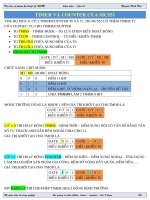
... THx=TLx=00H 0 T0: TIMER MODE1 – 16 BIT 0 T0: TIMER MODE2 – BIT – TRUYỀN DL 1 T0: COUNTER MODE1 – 16 BIT (0-65535) 1 T0: COUNTER MODE2 – BIT (0-255)  THANH GHI TCON – TIMER CONTROL TF1 TR1 TF0 ... MAIN1: BIT P3.3 BIT P3.6 BIT P3.7 JNB JNB JNB MAIN: BIT P3.0 BIT P3.1 BIT P3.2 START1,LB_ START1 STOP1,LB_ STOP1 Bộ môn điện tử công nghiệp ;C0 VÀ C1 LÀ COUNTER giảng vi điều khiển: timercounter ... DUNG COUNTER0 - HIEN THI KET QUA 16 BIT RA LED DON ORG MOV TMOD,#00000101B ;COUNTER0 C/T=1 SETB TR0 ;CHO TIMER0 /COUNTER0 DEM MOV TL0,#240 Bộ môn điện tử công nghiệp giảng vi điều khiển: timer – counter...
  • 41
  • 241
  • 0
TIMER VÀ COUNTER CỦA MCS51 docx

TIMER VÀ COUNTER CỦA MCS51 docx

Ngày tải lên : 07/08/2014, 22:20
... THx=TLx=00H 0 T0: TIMER MODE1 – 16 BIT 0 T0: TIMER MODE2 – BIT – TRUYỀN DL 1 T0: COUNTER MODE1 – 16 BIT (0-65535) 1 T0: COUNTER MODE2 – BIT (0-255)  THANH GHI TCON – TIMER CONTROL TF1 TR1 TF0 ... MAIN1: BIT P3.3 BIT P3.6 BIT P3.7 JNB JNB JNB MAIN: BIT P3.0 BIT P3.1 BIT P3.2 START1,LB_ START1 STOP1,LB_ STOP1 Bộ môn điện tử công nghiệp ;C0 VÀ C1 LÀ COUNTER giảng vi điều khiển: timercounter ... TRÌNH (H1) MOV TMOD,#000000001B ;TIMER0 MOD1 DEM 16 BIT LỆNH KHỞI TẠO TIMER0 : MOD ĐẾM 16 BIT, CHẾ ĐỘ TIMER, TIMER1 THÌ KHÔNG QUAN TÂM (H2) DELAY: SETB TR0 ;CHO TIMER0 DEM TÊN CỦA CHƯƠNG TRÌNH...
  • 36
  • 304
  • 0
Báo cáo y học: "Differences between homicide and filicide offenders; results of a nationwide register-based case-control study" ppt

Báo cáo y học: "Differences between homicide and filicide offenders; results of a nationwide register-based case-control study" ppt

Ngày tải lên : 11/08/2014, 17:20
... individual PCL-R items as shown in Table Discussion The novel results of this nationwide register- based casecontrol study reinforced the general finding that filicide offenders are a distinct group ... shallow affect, callous/lack of empathy, poor behavioral controls, and failure to accept responsibility All of these except poor behavioral control compose the Cooke's factor deficient affective ... have successfully reported across this margin of classifications [18,26] The NAMA instructs and controls the standards of the examinations, and overall quality and reliability of Finnish forensic...
  • 8
  • 553
  • 0
LẬP TRÌNH ỨNG DỤNG VỚI TIMER VÀ COUNTER

LẬP TRÌNH ỨNG DỤNG VỚI TIMER VÀ COUNTER

Ngày tải lên : 11/10/2014, 08:55
... DỤNG VỚI TIMERCOUNTER I ỨNG DỤNG CỦA TIMER TRONG LẬP TRÌNH Tổng quát loại TIMER PLC S7_300 Bộ Timer xung ON -> Time -> OFF (AR) Bộ Timer xung mở rộng ON->Time->OFF(NAR) Bộ Timer On delay OFF ... ->Time->ON(AR) Bộ Timer On delay OFF ->Time ->ON(NAR) Bộ Timer phát sườn xuống Bộ Timer xung dạng cuộn dây Bộ Timer xung mở rộng dạng cuộn dây Bộ Timer xung On delay dạng cuộn dây Bộ Timer xung On ... TRÌNH ỨNG DỤNG VỚI TIMERCOUNTER II ỨNG DỤNG CỦA COUNTER TRONG LẬP TRÌNH * Bộ đếm lên xuống S_CUD www.topedu.com.vn BUỔI LẬP TRÌNH ỨNG DỤNG VỚI TIMERCOUNTER II ỨNG DỤNG CỦA COUNTER TRONG LẬP...
  • 18
  • 868
  • 2
MICROARRAY FOR SINGLE PARTICLE TRAP WITH ADDRESSABLE CONTROL BASED ON NEGATIVE DIELECTROPHORESIS

MICROARRAY FOR SINGLE PARTICLE TRAP WITH ADDRESSABLE CONTROL BASED ON NEGATIVE DIELECTROPHORESIS

Ngày tải lên : 11/09/2015, 10:01
... 106 6.16 Addressable control 107 6.17 Schematic of addressable control 108 6.18 Schematic of addressable control ... in order to meet the requirement of control of large number of traps By using this technique, a device with n by n traps can be controlled separately by 2n control points Finally, the fabrication ... difficult to control such a large microarray because each trap needs eight control points Figure 2.15: Planar Quadrupole Electrodes[53] Figure 2.16: Octopole Electrodes[53] To solve the control problem,...
  • 163
  • 280
  • 0
AN1326   using the MCP4728 12 bit DAC for LDMOS amplifier bias control applications

AN1326 using the MCP4728 12 bit DAC for LDMOS amplifier bias control applications

Ngày tải lên : 11/01/2016, 16:56
... INPUT REGISTER A VSS SDA SCL I2C Interface Logic EEPROM B INPUT REGISTER B EEPROM C INPUT REGISTER C EEPROM D INPUT REGISTER D RDY/BSY Internal VREF (2.048V) OUTPUT REGISTER A UDAC OUTPUT REGISTER ... OUTPUT REGISTER C UDAC OUTPUT REGISTER D VREF Selector VDD FIGURE 4: UDAC VREF A STRING DAC A VREF B Gain Control STRING DAC B VREF C Gain Control STRING DAC C VREF D Output Logic Gain Control ... Logic Gain Control Gain Control STRING DAC D VREF OP AMP A Power Down Control VOUT A Output Logic OP AMP B Power Down Control VOUT B Output Logic OP AMP C Power Down Control OP AMP D VOUT C Output...
  • 12
  • 734
  • 0

Xem thêm