steel rigid frames manual design and construction


API 2510 – 2001 design and construction of LPG installations
Ngày tải lên :
27/03/2014, 14:08
...
DESIGN AND CONSTRUCTION OF
LPG
INSTALLATIONS 3
4 Design
of
LPG
Vessels
4.1
APPLICABLE DESIGN CONSTRUCTION
CODES
4.1.1
Vessels shall meet the requirements
of
the ASME
Boiler and ...
6 Foundations and Supports for LPG
Storage Vessels and Related Piping
6.1
APPLICABLE CODES AND SPECIFICATIONS
The materials, principles, methods, and details
of
design
and construction ...
LOADING, AND UNLOADING
EQUIPMENT
9.3.1
Pumps
9.3.1.1
Pumps may be centrifugal, reciprocating, gear, sub-
mersible or may be another type designed for handling
LPG.
The design pressure and construction...
- 29
- 1.7K
- 1

earth and rock fill dams general design and construction considerations
Ngày tải lên :
28/04/2014, 11:50
... Design
EARTH AND ROCK-FILL DAMS—GENERAL DESIGN
AND CONSTRUCTION CONSIDERATIONS
1. Purpose. This manual presents fundamental principles underlying the design and construction of
earth and rock-fill ... spillway
and outlet works on rock rather than in the embankment
or foundation overburden.
4-7. Coordination Between Design and
Construction
a. Introduction. Close coordination between design
and construction ... continuously evalu-
ated and “re-engineered,” as required, during construction,
to ensure that the final design is compatible with condi-
tions encountered during construction. Design and design
review...
- 78
- 500
- 0

Building design and construction handbook ppt
Ngày tải lên :
27/06/2014, 22:20
... 4.68
4.46 Effects of Steel Production Methods / 4.70
4.47 Effects of Hot Rolling / 4.72
4.48 Effects of Punching and Shearing / 4.73
4.49 Corrosion of Iron and Steel / 4.74
4.50 Steel and Steel Alloy ... building design
and construction must be made. Building designers and constructors should be alert
to these advances and learn how to apply them skillfully.
One advance of note to building design ... ALLOYS
4.40 Types of Irons and Steels / 4.52
4.41 Properties of Structural Steels / 4.58
4.42 Heat Treatment and Hardening of Steels / 4.61
4.43 Effects of Grain Size / 4.62
4.44 Steel Alloys / 4.62
4.45...
- 1.7K
- 1.7K
- 0
Aluminium Design and Construction - Chapter 12 ppt
Ngày tải lên :
22/07/2014, 18:22
... Standard BS.8118 fails to give
guidance on the fatigue of bolts used in aluminium structures.
12.9.2 Endurance curves for steel bolts
Aluminium designers can make use of the fatigue data for steel ... line 2 depends on the relative axial
stiffnesses of the bolt and the clamped plate material. Fisher and Struik
suggest that for all -steel construction s lies in the range 0.05–0.10. This
tallies ... check, the designer has
essentially two options. One is to increase the section, thus reducing
the level of stress. This increases weight and cost, and may be highly
inconvenient if the design is...
- 18
- 317
- 0

Aluminium Design and Construction - Chapter 11 docx
Ngày tải lên :
22/07/2014, 18:22
... 25°C.
3. Columns 3 and 4 give the room temperature curing time to achieve =1 and =10 N/mm
2
, when tested at 23°C.
4. Columns 5 and 6 give typical average strengths when tested at 23°C and 80°C, after ... taken as 0.9 in
steel design. In aluminium construction, because of the lower modulus
of the aluminium plates, a larger proportion of T
1
is used up in increasing
the bolt tension, and the drop ... First,
we only require a designer to check bearing on the ply, as in USA and
Canada, and ignore bearing on the fastener. Secondly, our expression
for p
p
includes both the proof and the ultimate stress...
- 33
- 373
- 0
Aluminium Design and Construction - Chapter 10 pps
Ngày tải lên :
22/07/2014, 18:22
... and OY is selected, enabling
expressions for S
x
and S
y
(in terms of w and z) to be obtained as follows:
(10.6)
where: A
E
=area of an element taken positive for compression material
and ... of the two values I/y
c
and I/y
t
, where I
is the inertia about the axis considered, and y
c
and y
t
are the perpendicular
distances from the extreme compressive and tensile fibres of the ... into convenient
elements, and obtain expressions in terms of w for the plastic moduli
S
x
and S
y
about Ox and Oy, as follows:
(10.3)
where A
E
=area of an element, and x
E
, y
E
=coordinates...
- 27
- 311
- 0
Aluminium Design and Construction - Chapter 9 docx
Ngày tải lên :
22/07/2014, 18:22
... heavy
gauge (hot-rolled) steel. It becomes more likely as the thickness decreases,
and for thin-walled members it is often critical, as also in light gauge
(cold-formed) steel. The checking of ... I
p
=polar inertia about shear centre S,
H=warping factor, and l=effective buckling length.
Here , Ip and H may be based on the gross section, and can be
found with the aid of Chapter 10. The effective ... bending moments at their ends due
to joint rigidity. These ‘secondary’ moments can be significant and the
question arises as to whether to allow for them in design.
Linear elastic analysis readily...
- 26
- 326
- 0
Aluminium Design and Construction - Chapter 8 doc
Ngày tải lên :
22/07/2014, 18:22
... yield stress
and the 0.2% proof stress respectively for the two materials. Typically,
the diagram might be looked on as comparing mild steel and 6082-T6
aluminium.
Moment levels Zp
°
and Sp
°
... [26].
Figure 8.1 Comparison of the curves relating bending moment M and curvature 1/R for
steel (1) and aluminium (2) beams of the same section and yield/proof stress.
Copyright 1999 by Taylor & Francis ... simple
British Standard rule (expression (8.6)) and those obtained using the
more accurate treatments given in 1 and 2 above. The figure relates to a
particular form of extruded shape and shows how...
- 33
- 389
- 0
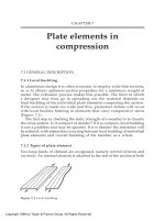
Aluminium Design and Construction - Chapter 7 pps
Ngày tải lên :
22/07/2014, 18:22
... 7.18) given by:
Figure 7.17 ‘Standard’ reinforcement.
Copyright 1999 by Taylor & Francis Group. All Rights Reserved.
7.1) by g. The resulting design curves of ò
f
and ß
s
plotted against
... element.
Stress-pattern at failure, and assumed
effective section. N=non-welded,
W=with edge-welds.
Figure 7.5 Slender outstand. Stress-
pattern at failure, and assumed effective
section. N=non-welded, ... becomes operative when:
Non-welded outstand ò > 12.1
Welded outstand ß > 12.9 .
The effect of so doing is shown by the broken curve in Figure 7.7.
Chapters 8 and 9 explain when it is necessary...
- 22
- 340
- 0

Aluminium Design and Construction - Chapter 6 pptx
Ngày tải lên :
22/07/2014, 18:22
... first two of these are needed for member design
and are selected as follows:
k
z1
shear force resistance in beams (Section 8.3);
local failure in tension and compression members (Section 9.3).
k
z2
moment ... prototype.
Designers should also be aware of the locked-in (‘residual’) stresses
in welded components, even though these are not directly considered
in the design process. As with steel, there ... versus weld size therefore dips
suddenly at w=8 mm and then climbs, as illustrated in Figure 6.14
(broken line). This would be hard to codify, and for design we
conservatively draw a horizontal line...
- 24
- 288
- 0
Aluminium Design and Construction - Chapter 5 pps
Ngày tải lên :
22/07/2014, 18:22
... Reserved.
CHAPTER 5
Limit state design and
limiting stresses
British Standard BS.8118 follows steel practice in employing the limit
state approach to structural design, in place of the former ... and
m
equal to 1.3 and 1.2 respectively, giving a minimum
LFC of 1.56. This implies that the member could just withstand a static
overload of 56% before collapsing. The aim of limit state design ... loading, is also more critical than for steel.
In the USA, when limit state design is mentioned, it is given the
(logical) title ‘Load and Resistance Factor Design (LRFD).
5.1.2 Definitions
Some...
- 15
- 292
- 0
Aluminium Design and Construction - Chapter 4 pptx
Ngày tải lên :
22/07/2014, 18:22
... the standard fails to
give specified values and one has to make do with ‘typical’ ones, which
are not binding on the manufacturer.
The compressive proof stress is never recorded, and a designer ... product, temper and thickness. It is essential for a designer to refer
to an appropriate standard to find precise strength values for the materials
he/she is planning to use. Relevant standards, covering ... D)
of the alloy and the severity of the environment [9]. The data on ratings
A, B and C are taken from BS.8118.
In welded construction, it is possible for the weld filler material, and
hence the...
- 28
- 365
- 1
Aluminium Design and Construction - Chapter 3 potx
Ngày tải lên :
22/07/2014, 18:22
... Standard BS.8118 recommends a standard treatment,
and when this is used a stated design value may be taken for the slip-
factor (Section 11.2.6).
Tightening procedures are as for joints in steel, ... both
bolt-head and nut. With aluminium and stainless steel bolts, these would
normally be of aluminium, in a comparable alloy to the parts being
joined. However, the British Standard also allows ... Inert Gas) and TIG (Tungsten Inert Gas).
MIG is the more widely employed, especially for heavier construction,
using weld geometries and preparations similar to those in structural
steel. TIG...
- 19
- 444
- 0

Aluminium Design and Construction - Chapter 2 potx
Ngày tải lên :
22/07/2014, 18:22
... is
generated by a tipped mandrel carried on the inner ram and passing
through a hole in the billet. The method is slow to set up and more
costly. Also there is a tendency for the long mandrel to deflect ... surface, concealed fixing and positive
interlock between adjacent planks. Figure 2.12 shows two designs by
British engineer Ron Cobden for truck chassis members, one welded
and the other bonded. ... the thousand, are in a special hard
heat-resisting steel, the aperture being machined by spark erosion. The
tooling cost for a straightforward structural die (non-hollow), 150 mm
wide and without...
- 17
- 339
- 0
Aluminium Design and Construction - Chapter 1 doc
Ngày tải lên :
22/07/2014, 18:22
... (John B.), 1921–
Aluminium design and construction/ J.B.Dwight.
p. cm.
Includes bibliographical references and index.
ISBN 0-419-15710-7 (Print Edition)
1. Aluminum construction. 2. Aluminum. ... Application of HAZ data to design
6.6.1 Design of members
6.6.2 Design of joints
Copyright 1999 by Taylor & Francis Group. All Rights Reserved.
to be absorbed in the brain, and that this in turn ... compares with steel as
follows:
Pure aluminium E=69 kN/mm
2
Structural steel E=205 kN/mm
2
while the value for wrought alloys lies in the range 69–72 kN/mm. For
design purposes British Standard BS.8118...
- 39
- 332
- 0


Tìm thêm:
- hệ việt nam nhật bản và sức hấp dẫn của tiếng nhật tại việt nam
- xác định các mục tiêu của chương trình
- xác định các nguyên tắc biên soạn
- khảo sát các chuẩn giảng dạy tiếng nhật từ góc độ lí thuyết và thực tiễn
- khảo sát chương trình đào tạo của các đơn vị đào tạo tại nhật bản
- khảo sát chương trình đào tạo gắn với các giáo trình cụ thể
- xác định thời lượng học về mặt lí thuyết và thực tế
- tiến hành xây dựng chương trình đào tạo dành cho đối tượng không chuyên ngữ tại việt nam
- điều tra đối với đối tượng giảng viên và đối tượng quản lí
- điều tra với đối tượng sinh viên học tiếng nhật không chuyên ngữ1
- khảo sát thực tế giảng dạy tiếng nhật không chuyên ngữ tại việt nam
- khảo sát các chương trình đào tạo theo những bộ giáo trình tiêu biểu
- nội dung cụ thể cho từng kĩ năng ở từng cấp độ
- xác định mức độ đáp ứng về văn hoá và chuyên môn trong ct
- phát huy những thành tựu công nghệ mới nhất được áp dụng vào công tác dạy và học ngoại ngữ
- mở máy động cơ lồng sóc
- mở máy động cơ rôto dây quấn
- các đặc tính của động cơ điện không đồng bộ
- hệ số công suất cosp fi p2
- đặc tuyến hiệu suất h fi p2