programmable logic controllers hardware and programming max rabiee pdf

Tài liệu PLC MELSEC System Q Programmable Logic Controllers
Ngày tải lên :
15/10/2013, 16:28
... Q01CPU
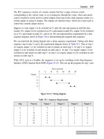
Capacity Max. 8k steps Max. 8k steps Max. 14k steps
Number of files
Scannable SFC program: 1 file 1
Number of blocks Max. 128 blocks
Number of SFC steps Max. 1024 steps for all blocks, max. 128 ... of branches Max. 32
Number of concurrently active steps
Max. 1024 steps for all blocks
Max. 128 steps for one block
(including HOLD steps)
Number of operation output sequence
steps
Max. 2k steps ... simultaneously in all
blocks and the maximum number of active steps in a single block.
CPU Module Model name
Number of Steps That Can Be
Executed Simultaneously in All Blocks
Maximum Number of Active
Steps...
- 168
- 1.8K
- 1

Tài liệu Programmable logic controllers Basic level TP301 – Textbook ppt
Ngày tải lên :
22/12/2013, 18:16
... required entirely different programming.
Since 1992, an international standard now exists for programmable logic
controllers and associated peripheral devices (programming and diag-
nostic tools, ... this standard were adopted unamended as European
Standard EN 61 131, Parts 1 to 3.
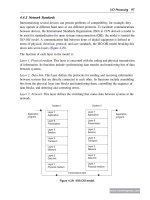
The purpose of the new standard was to define and standardise the de-
sign and functionality of a PLC and the ... standardised housing.
The hardware design for a programmable logic controller is such that it
is able to withstand typical industrial environments as regard signal lev-
els, heat, humidity, and...
- 214
- 690
- 4

Báo cáo khoa học: "CONCURRENT PARSING IN PROGRAMMABLE LOGIC ARRAY PROBLEMS AND PROPOSALS" docx
Ngày tải lên :
31/03/2014, 17:20
... combinational logic and
feedback some of the outputs to inputs The
circuit's structure is topologically regular, has
a reasonable topological interface as a subsystem,
and is of a shape and size ... circuit elements called the
AND plane. The AND plane generates specific logic
combinations of the inputs. The outputs of the
AND plane leave at right angles to its input and
run horizontally through ... understood than programming theory
and programming technique.
4. Note: It does not stand to question that
there is any problem which, in principle, could
not be solved by programming. It...
- 4
- 269
- 0

Programmable logic controllers 5ed P1
Ngày tải lên :
10/04/2014, 14:10
... arithmetic and logic unit (ALU) that is responsible for data manipulation and
carrying out arithmetic operations of addition and subtraction and logic operations of
AND, OR, NOT, and EXCLUSIVE-OR.
User
program
RAM
CPU
System
ROM
Data
RAM
Battery
Input/
output
unit
Clock
Address ... of
www.newnespress.com
Programmable Logic Controllers 13
•
Random-access memory (RAM) is used for data. This is where information is stored on
the status of input and output devices and the values of timers and ... completed.
1.1.2 The Programmable Logic Controller
A programmable logic controller (PLC) is a special form of microprocessor-based controller
that uses programmable memory to store instructions and to implement...
- 50
- 805
- 11

Programmable logic controllers 5ed P2
Ngày tải lên :
10/04/2014, 14:12
... termed a combinational logic system.
Useful combinational logic systems, which we will meet in Chapter 5, are the AND gate, the
OR gate, the NOT gate, the NAND gate, the NOR gate, and the XOR gate. ... listeners, talkers, and controllers.
Listeners are devices that accept data from a bus; talkers place data, on request, on the
bus; and controllers manage the flow of data on the bus and provide processing ... to carry data and
commands between the various devices connected to the bus, five lines are used for control
and status signals, three are used for handshaking between devices, and eight are...
- 50
- 730
- 8
Programmable logic controllers 5ed P3
Ngày tải lên :
10/04/2014, 14:14
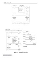
... assembly from NOT, AND, and OR gates, as shown in
Figure 5.34.
The input to the bottom AND gate is:
A and
B
and so its output is:
A
Á
B
The input to the top AND gate is:
A and B
Input A
Input ... block.
www.newnespress.com
Ladder and Functional Block Programming 127
CHAPTER 6
IL, SFC, and ST Programming Methods
This chapter continues from the previous chapter and discusses the other IEC 1131-3
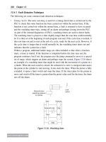
programming ... circuit, (b) a NOT logic gate with a ladder rung,
and (c) a high output when no input to A.
www.newnespress.com
Ladder and Functional Block Programming 119
the input power rails and stringing the...
- 50
- 776
- 8
Programmable logic controllers 5ed P4
Ngày tải lên :
10/04/2014, 14:16
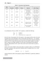
... relay or marker and the notation M100, M101, and so on. Siemens uses the term
flag and the notation F0.0, F0.1, and so on. Telemecanique uses the term bit and the notation
B0, B1, and so on. Toshiba ... uses the term internal relay and the notation R000, R001, and so
on. Allen-Bradley uses the term bit storage and notation in the PLC-5 of the form B3/001,
B3/002, and so on.
7.2 Ladder Programs
With ... lifted
ValvePump
X400
X401
Y430
X402
LD
OR
AND
OUT
END
X400
X402
X401
Y430
Figure 6.9: Valve operation program.
www.newnespress.com
IL, SFC, and ST Programming Methods 155
With an Allen-Bradley PLC, the terms latch and unlatch...
- 50
- 571
- 7
Programmable logic controllers 5ed P5
Ngày tải lên :
10/04/2014, 14:18
... over again, and count for 10 pulses.
Figure 10.4a shows how the preceding program and its program instruction list would appear
with a Mitsubishi PLC and a CTU counter. The reset and counting ... bit is 1 when the input logic makes the up-
counter rung 1 and 0 when the rung is 0. The count-down (CD) enable bit is 1 when the
input logic makes the down-counter rung 1 and 0 when the rung is ... (ii) T
D. (i) F (ii) F
Problems 3 and 4 refer to Figure 8.11, which shows a ladder diagram with inputs (In 1, In 2,
and In 3), outputs (Out 1, Out 2, and Out 3), and a jump-to-subroutine instruction.
3....
- 50
- 670
- 8
Programmable logic controllers 5ed P6
Ngày tải lên :
10/04/2014, 14:20
... They operate in synchronism with the same program
and compare input and output signals, the results of logic operations, counters, and the like,
and automatically go into a safe-stop condition ... shift register with internal
relays IR 1, IR 2, IR 3, and IR 4, with three inputs (In 1, In 2, and In 3) and four outputs (Out
1, Out 2, Out 3, and Out 4).
6. Decide whether each of these statements ... event is detected
and remains on, output 3 is switched on when the third event is detected and remains
on, output 4 is switched on when the fourth event is detected and remains on, and all
outputs...
- 50
- 634
- 6
Programmable logic controllers 5ed P7
Ngày tải lên :
10/04/2014, 14:22
... making the workplace
safe and without risks to health and ensuring that plant and machinery are safe and that
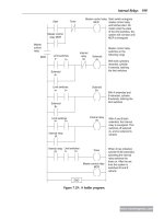
safe systems of work are set and followed. An important standard relevant to PLCs is ... one area of operation and separated by a page break from the next file. The
file that follows controls a bundle-cutting band saw and involves motor controls, desk
lamps, and a small state transition ... to Andrew Parr for supplying it. It illustrates the way a
program file is documented to aid in clarification and the safety and fault indication
procedures that are used. Note that the right-hand...
- 50
- 675
- 5


Questions to .NET and Programming in C#
Ngày tải lên :
21/08/2012, 15:55
... standard
output.
b) The code will compile and run
but nothing will be return on
the standard output.
d) The code will compile and
run and the word “Default”
will be written to the standard ... code compiles and "5,
Sub" is printed on the
standard output.
b) The code compiles and "5,
Super" is printed on the
standard output.
d) The code compiles and "2, ... class Q21 {
2. int maxElements;
3. void Q21() {
4. maxElements = 100;
5. System.out.println(maxElements);
6. }
7. Q21(int i) {
8. maxElements = i;
9. System.out.println(maxElements);
10....
- 18
- 1.3K
- 8

Questions to .NET and Programming in C#
Ngày tải lên :
29/08/2012, 16:37
...
successfully and
output the
following text:
In Try
In Finally
b) The code will compile successfully
and output the following text:
In Try
d) The code will
compile successfully
and output ... true.
[1.5]
a) Only statement II is true.
c) Statement III and I
are true.
b) Statement II and III are true. d) Statement II and I
are true.
215. To declare a web service the class ...
a compile time error at
line 12 and line 13.
b) The code will compile successfully
and outputs will be:
1
2
d) The code will compile
successfully and
output will be:0
1
151....
- 36
- 1.3K
- 5
- programmable logic controllers hardware and programming
- programmable logic controllers hardware and programming 2nd edition
- programmable logic controllers hardware and programming download
- programmable logic controllers hardware and programming free download
- programmable logic controllers hardware and programming 3rd edition pdf
- programmable logic controllers hardware and programming 2nd edition pdf
- programmable logic controllers hardware and programming pdf
- mitsubishi fx programmable logic controllers applications and programming
- programmable logic controllers hardware and programming by max rabiee pdf
Tìm thêm:
- hệ việt nam nhật bản và sức hấp dẫn của tiếng nhật tại việt nam
- xác định các mục tiêu của chương trình
- xác định các nguyên tắc biên soạn
- khảo sát các chuẩn giảng dạy tiếng nhật từ góc độ lí thuyết và thực tiễn
- khảo sát chương trình đào tạo của các đơn vị đào tạo tại nhật bản
- khảo sát chương trình đào tạo gắn với các giáo trình cụ thể
- xác định thời lượng học về mặt lí thuyết và thực tế
- tiến hành xây dựng chương trình đào tạo dành cho đối tượng không chuyên ngữ tại việt nam
- điều tra đối với đối tượng giảng viên và đối tượng quản lí
- điều tra với đối tượng sinh viên học tiếng nhật không chuyên ngữ1
- khảo sát thực tế giảng dạy tiếng nhật không chuyên ngữ tại việt nam
- khảo sát các chương trình đào tạo theo những bộ giáo trình tiêu biểu
- nội dung cụ thể cho từng kĩ năng ở từng cấp độ
- xác định mức độ đáp ứng về văn hoá và chuyên môn trong ct
- phát huy những thành tựu công nghệ mới nhất được áp dụng vào công tác dạy và học ngoại ngữ
- mở máy động cơ lồng sóc
- mở máy động cơ rôto dây quấn
- các đặc tính của động cơ điện không đồng bộ
- hệ số công suất cosp fi p2
- đặc tuyến hiệu suất h fi p2