programmable logic controllers 4th edition frank d petruzella pdf

Tài liệu PLC MELSEC System Q Programmable Logic Controllers
Ngày tải lên :
15/10/2013, 16:28
... Word J
\ G0 to J \ G65535 Decimal
Fixed
(depending
on
intelligent
function
module)
ã Exist in each
intelligent function
module.
ã
indicates the I/O
No. /16, and
changes depending
on the model ... performed until the START destination block is deactivated after its
execution has ended.
(c) When the START destination block is deactivated after its execution has ended, only the
transition condition ... of
1 to 239 and 254.
Special module
direct
Buffer register Word J
\ G0 to J \ G65535 Decimal
Fixed
(depending
on
intelligent
function
module)
ã Exist in each special
function
module/intelligent
function...
- 168
- 1.8K
- 1

Tài liệu Programmable logic controllers Basic level TP301 – Textbook ppt
Ngày tải lên :
22/12/2013, 18:16
... readable numeral repre-
sentation was introduced; i.e. the binary coded decimal notation, the so-
called BCD code (binary coded decimal). With this BCD code, each indi-
vidual digit of the decimal ... this standard were adopted unamended as European
Standard EN 61 131, Parts 1 to 3.
The purpose of the new standard was to define and standardise the de-
sign and functionality of a PLC and the ... table
Fig. B3.7
AND function
TP301 ã Festo Didactic
B-IV
TP301 ã Festo Didactic
B-26
Chapter 3
bd
a
d
a
bd
d
ac
bd
ac
d
Assuming that a drilled hole is read as a 1-signal,...
- 214
- 691
- 4


Programmable logic controllers 5ed P1
Ngày tải lên :
10/04/2014, 14:10
... te nded to develop its own vers ions and so
an international standard has been adopted for ladder programming and indeed all
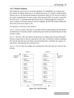
the methods used for programming PLCs. The standar d, published in ... CHAPTER 2
Input/Output Devices
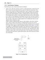
This chapter is a brief consideration of typical input and output devices used with PLCs. The
input devices considered include digital and analog devices such as mechanical ... at knowle dge of pro gramming t o wr ite prog rams for PLCs ,
ladder programmin g was de veloped. Most PLC manufacturers adopt ed this method of
www.newnespress.com
Programmable Logic Controllers...
- 50
- 806
- 11

Programmable logic controllers 5ed P2
Ngày tải lên :
10/04/2014, 14:12
... just divided
31 by 2, that is, 2
1
, and found 1 left over for the 2
0
digit. The last division gives the MSB
because the 31 has then been divided by 2 four times, that is, 2
4
, and the remainder ... transmitted or received per second. However, not all the transmitted bits can
be used for data; some have to be used to indicate the start and stop of a serial piece of data,
often termed flags, and ... because there is an odd number of 1s. To make
both these odd parity, the extra bit added at the end in the first case is 1 and in the second
case 0, that is, we have 01001001 and 01101000. Thus when...
- 50
- 730
- 8
Programmable logic controllers 5ed P3
Ngày tải lên :
10/04/2014, 14:14
... are scanned and copied into RAM, then fetched and decoded,
and all program instructions are executed in sequence and output instructions copied to
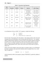
RAM. Then all the outputs are updated before repeating ... proposed and is being widely adopted. Table 6.1
shows some of the codes used by manufacturers and the proposed standard for instructions
used in this chapter (see later chapters for codes for ... ladder diagram. Which of the diagrams showing inputs and output
signals would occur with that ladder program?
24. Figure 5.57 shows a ladder diagram. Which of the diagrams showing inputs and...
- 50
- 776
- 8
Programmable logic controllers 5ed P4
Ngày tải lên :
10/04/2014, 14:16
... its
normally closed contacts and unlatches the solenoid Aỵ. Solenoid A thus retracts. When it
has retracted and opened the normally closed contacts a, solenoid Bỵ becomes unlatched
and cylinder B retracts.
A
B
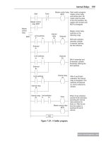
a– ... set and reset an internal
relay, for which the term flip-flop is used.
END
Start
b–
A+ b+
a–
Cylinder A extends,
latched until b+
activated
Cylinder B extends,
latched until a–
activated
Limit ... been turned on and are off if the power is off. It would be possible to devise a
ladder diagram that has individually latched controls for each such output. However, a
simpler method is to use...
- 50
- 571
- 7
Programmable logic controllers 5ed P5
Ngày tải lên :
10/04/2014, 14:18
... both cylinders
retracted, cylinder
A extends, latching
the limit switches
With A extended and
B retracted, cylinder
B extends, latching the
limit switches
With A and B both
extended, the internal
relay ... number of pegs protruded (Figure 10.13). When the cylinder rotated, contacts
aligned with the pegs were closed when the peg impacted them and opened when the peg had
passed. Thus for the arrangement ... sensor has to be counted and used to control the
deflector. Figure 10.8b shows the ladder program that could be used, with Mitsubishi
notation.
Counter
S_CD
CD
Q
S
PV
R
CV
CV_BCD
Set counter
Quantity
Input...
- 50
- 670
- 8
Programmable logic controllers 5ed P6
Ngày tải lên :
10/04/2014, 14:20
... switched on when the first event is
detected and remains on, output 2 is switched on when the second event is detected
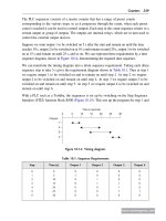
and remains on, output 3 is switched on when the third event is detected and ... termed closed loop control.
ADD
ADD
SOURCE A N7.1
SOURCE B N7.3
DEST N7.5
ADD_1
EN
IN1
IN2
OUT
ENO
(b)(a)
Figure 12.9: ADD: (a) Allen-Bradley format, and (b) Siemens format.
BIN
(a)
Source
Destination
BCD ... format.
BIN
(a)
Source
Destination
BCD S
S
Source
Destination
EN
IN
ENO
BCD_I
EN
IN OUT
ENO
I_BCD
(b)
CONVERT TO BCD
SOURCE A N7.3
DESTINATION O:10
FRD
(c)
CONVERT FROM BCD
SOURCE A I:1
DESTINATION N7.3
TOD
D
D
OUT
Figure...
- 50
- 634
- 6
Programmable logic controllers 5ed P7
Ngày tải lên :
10/04/2014, 14:22
... page titles.
www.newnespress.com
Designing Systems 307
A. DO-THEN-DO-ENDDO
B. IF-THEN-ELSE-ENDIF
C. WHILE-DO-ENDWHILE
D. Not described by A, B, or C
2. Decide whether each of these statements ... 5 IR 6 Reset
LED A–
LED A–
IR 5
IR 6
LED B–
LED B–
LED C–
LED C–
END
If A– output occurs, IR 4 closes
and is latched on. LED A– is
then on. LED A– is not on
unless IR 4 is closed
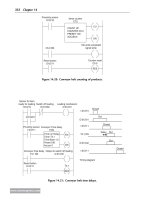
If B– output ... indicates exit barrier
is up
X401
M100
X404
M101
X405 indicates exit barrier
is down
T450
K10
T450
T451
T451
END
LD
OR
ANI
OUT
LD
OUT
K
LD
OUT
LD
OR
ANI
ANI
OUT
LD
OR
ANI
ANI
OUT
LD
OUT
K
LD
OUT
LD
OR
ANI
ANI
OUT
END
X400
Y430
M100
Y431
Y430
X401
T450
10
T450
M100
M100
Y431
X402
Y430
Y431
X403
ANI
Y432
M101
Y433
Y432
X404
T451
10
T451
M101
M101
Y433
X405
Y432
Y433
Coin...
- 50
- 675
- 5
Programmable logic controllers 5ed P8
Ngày tải lên :
10/04/2014, 14:24
... controllers.
See entries at PLC
programming devices, 4, 15–16
programming methods.
See function block diagrams
(FBDs); IL (instruction
lists); ladder programming
(LAD) and ladder diagrams;
SFCs (sequential function
charts); ... gate
Input
OutputA
1
Input
Output
A
NAND gate
A
B
Output
Inputs
&
A
B
Output
Inputs
NOR Gate
A
B
Output
Inputs
>
1
A
B
Output
Inputs
www.newnespress.com
Appendix: Symbols 365
ladder programming (LAD) and
ladder diagrams
(Continued)
SET ... 1 AND 3
Empty 1
Valve 1
Empty 2
Valve 2
Limit switch 2 Limit switch 4
Emptied 1 Emptied 2
Limit switch 2 AND 4
Mixer
Mix
liquids
Time elapsed 100 s
Valve 3
Mixed
liquids
Limit switch 5
End
Figure...
- 48
- 776
- 6

programmable logic controllers ann series cpu modules
Ngày tải lên :
30/09/2014, 22:27
... ≥ AC 160 ≥ DC 3.5 or DC 5 ≥ DC 3.5 or DC 5 ≥ DC 3.5 or DC 5
Current (mA) ≥ AC 5.5 ≥ DC 1.0 ≥ DC 1.0 ≥ DC 1.0
ONOFF
Voltage (V) ≥ AC 70 ≥ DC 1.1 or DC 2 ≥ DC 1.1 or DC 2 ≥ DC 1.1 or DC 2
Current ... —
Rated Input Current (mA) 4 / 10 4 / 10 4 / 10
OFFON
Voltage (V) ≥ DC 9.5 ≥ DC 9.5 ≥ DC 9.5
Current (mA) ≥ DC 2.6 ≥ DC 2.6 ≥ DC 3
ONOFF
Voltage (V) ≤ DC 6 ≤ DC 6 ≤ DC 6
Current (mA) ≤ DC 1 ≤ DC ... uploads/downloads via the Internet
using standard software.
■ Fast response times — 480 words exchanged per protocol.
■ Easy-to-use integrated bus cable diagnostics.
MELSEC A Ethernet Modules
Specifications
AJ71QE71N-B5T...
- 66
- 369
- 0

VHDL Programming by Example 4th Edition
Ngày tải lên :
16/08/2012, 08:46
... learn how to
write good VHDL design descriptions. The goal is to provide enough VHDL
and design methodology information to enable a designer to quickly write
good VHDL designs and be able to verify ... Accellera.
And when the ASIC industry needed a standard way to convey gate-
level design data and timing information in VHDL, one of Accellera’s
progenitors (VHDL International) sponsored the IEEE VHDL ... Verilog HDL and VHDL industry standards teams
collaborated on the use of a common timing data such as IEEE 1497 SDF,
set register transfer level (RTL) standards and more to improve design
25
Behavioral...
- 497
- 1K
- 14


- programmable logic controllers 4th edition pdf
- programmable logic controllers 4th edition
- programmable logic controllers hardware and programming max rabiee pdf
- mitsubishi fx programmable logic controllers second edition applications and programming
- programmable logic controllers 4th edition frank d petruzella
- programmable logic controllers 4th edition solution manual