principles of electrical engineering and electronics by v k mehta pdf free download

Massachusetts Institute of Technology Department of Electrical Engineering and Computer Science
Ngày tải lên :
25/04/2013, 08:07
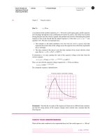
... take to execute (on average)?
(b) Now, modify the fibonacci() function by making the variables a, b, and c register variables.
Recompile and run the code. How long does a single iteration take ... Institute of Technology
Department of Electrical Engineering and Computer Science
6.087: Practical Programming in C
IAP 2010
Problem Set 3
Control flow. Functions. Variable scope. Static and global ... complex program is to develop it iteratively, solving one problem
at a time and testing it throroughly. For this problem, start with the following shell and then
iteratively add the missing components....
- 7
- 468
- 0


Tài liệu Principles And Applications Of Electrical Engineering P2 pdf
Ngày tải lên :
19/01/2014, 19:20
... the
polarities of the three resistors, and apply KVL to determine that
V
S
− v
1
− v
2
− v
3
= 0
The voltage divider rule tells us that
v
3
= V
S
ì
R
3
R
1
+ R
2
+ R
3
= 3 ì
8
10 + 6 + 8
= 1V
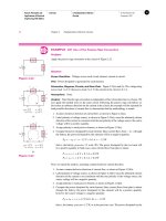
Comments: ... the voltage v
3
in the circuit of Figure 2.31.
v
3
v
2
–+
–
+
v
1
i
V
S
R
3
R
1
R
2
–
+
+
–
Figure 2.31
Solution
Known Quantities: Source voltage, resistance values
Find: Unknown voltage v
3
.
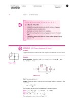
Schematics, ... source and resistor values.
Find: Obtain equations for each of the two circuits by applying KCL and KVL.
Schematics, Diagrams, Circuits, and Given Data: Figure 2.27.
V
S
R
1
V
1
R
2
(a)
–
+
V
2
–
+
–
+
I
R
1
(b)
R
2
I
1
I
2
V
I
S
–
+
Figure...
- 20
- 688
- 1

Tài liệu Principles And Applications Of Electrical Engineering P1 docx
Ngày tải lên :
19/01/2014, 19:20
... flow and to convert the electric energy to heat and light:
v
ab
= v
ba
or
v
1
= v
2
1.5 V
+
–
v
1
i
+
–
i
a
b
v
2
= v
ab
+
–
Illustration of Kirchhoff’s
voltage law: v
1
= v
2
Figure 2.5
Voltages ... Brief History of Electrical Engineering 9
1.5 Systems of Units 10
1.6 Special Features of This Book 11
2.1 Charge, Current, and Kirchhoff’s
Current Law 16
2.2 Voltage and Kirchhoff’s Voltage Law ... teacher and researcher in both
mechanical and electrical engineering.
Part I Circuits 21
Gustav Robert Kirchhoff
(1824–1887). Photo courtesy of
Deutsches Museum, Munich.
2.2 VOLTAGE AND KIRCHHOFF’S...
- 30
- 625
- 0

Tài liệu Principles And Applications Of Electrical Engineering P2 ppt
Ngày tải lên :
19/01/2014, 20:20
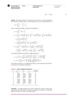
... each of the elements.
By applying KVL, you can verify that the sum of the voltages across the three
resistors equals the voltage externally provided by the battery:
1. 5V= v
1
+ v
2
+ v
3
and since, ... the
polarity of the voltage source). Following the passive sign convention, we label the
polarities of the three resistors, and apply KVL to determine that
V
S
− v
1
− v
2
− v
3
= 0
The voltage divider ... the voltage v
3
in the circuit of Figure 2.31.
v
3
v
2
–+
–
+
v
1
i
V
S
R
3
R
1
R
2
–
+
+
–
Figure 2.31
Solution
Known Quantities: Source voltage, resistance values
Find: Unknown voltage v
3
.
Schematics,...
- 20
- 667
- 0

Tài liệu Principles And Applications Of Electrical Engineering P1 doc
Ngày tải lên :
19/01/2014, 20:20
... State University
over several years.
1.4 BRIEF HISTORY OF ELECTRICAL
ENGINEERING
The historical evolution of electrical engineering can be attributed, in part, to
the work and discoveries of the ... equations for a linear resistive circuit by applying
Kirchhoff’s voltage law and Kirchhoff’s current law.
2.1 CHARGE, CURRENT, AND KIRCHHOFF’S
CURRENT LAW
The earliest accounts of electricity date from ... source voltage or current and the voltage or current it
depends on v
x
or i
x
, respectively—which can be any voltage or current in the
circuit.
+
_
v
S
Voltage controlled voltage source (VCVS) v
S
...
- 30
- 564
- 0


- operating system principles by galvin 7th edition pdf free download
- operating system principles by silberschatz galvin gagne pdf free download
- the magic of believing by claude m bristol pdf free download
- fundamentals of data structures in c by horowitz sahni and mehta pdf free download
- the 8051 microcontroller and embedded systems by muhammad ali mazidi pdf free download
- english for electrical engineering and electronics pdf
- data structures and algorithms in c by mark allen weiss pdf free download
- digital logic and computer design by morris mano solution pdf free download
- the department of electrical engineering and computer science at texas am universitykingsville
- electronic devices and circuits by salivahanan third edition pdf free download
- programmable logic controllers principles and applications by john w webb pdf free download
- fundamentals of electrical engineering and electronics by bl theraja pdf free download
- electronic devices and circuits by theodore f bogart pdf free download
- electronic devices and circuits by bogart 6th edition pdf free download
- nguồn mackenzio l davis susan j macten principles of environmental engineering and science
Tìm thêm:
- hệ việt nam nhật bản và sức hấp dẫn của tiếng nhật tại việt nam
- xác định các mục tiêu của chương trình
- xác định các nguyên tắc biên soạn
- khảo sát các chuẩn giảng dạy tiếng nhật từ góc độ lí thuyết và thực tiễn
- khảo sát chương trình đào tạo của các đơn vị đào tạo tại nhật bản
- khảo sát chương trình đào tạo gắn với các giáo trình cụ thể
- xác định thời lượng học về mặt lí thuyết và thực tế
- tiến hành xây dựng chương trình đào tạo dành cho đối tượng không chuyên ngữ tại việt nam
- điều tra đối với đối tượng giảng viên và đối tượng quản lí
- điều tra với đối tượng sinh viên học tiếng nhật không chuyên ngữ1
- khảo sát thực tế giảng dạy tiếng nhật không chuyên ngữ tại việt nam
- khảo sát các chương trình đào tạo theo những bộ giáo trình tiêu biểu
- nội dung cụ thể cho từng kĩ năng ở từng cấp độ
- xác định mức độ đáp ứng về văn hoá và chuyên môn trong ct
- phát huy những thành tựu công nghệ mới nhất được áp dụng vào công tác dạy và học ngoại ngữ
- mở máy động cơ lồng sóc
- mở máy động cơ rôto dây quấn
- các đặc tính của động cơ điện không đồng bộ
- hệ số công suất cosp fi p2
- đặc tuyến hiệu suất h fi p2