mạch lò vi sóng không nóng


Tài liệu RF và mạch lạc lò vi sóng P1 ppt
Ngày tải lên :
15/12/2013, 11:15
... the
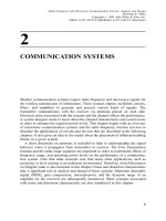
appendices. Chapter 2 provides an overview of wireless communication systems and
their characteristics.
8
INTRODUCTION
TABLE 1.4 Selected Applications of Microwave Solid-State Devices
Devices Applications ... carry the video information as well. Table 1.1 shows the
frequency bands used for commercial radio and television broadcasts.
In the case of digital transmission, a standard monochrome television ... terrestrial
communication system.
Figures 1.3 and 1.4 list selected devices used at RF and microwave frequencies.
Solid-state devices as well as vacuum tubes are used as active elements in RF and
microwave...
- 8
- 1.1K
- 10
Tài liệu RF và mạch lạc lò vi sóng P2 pdf
Ngày tải lên :
15/12/2013, 11:15
... illustrated in Figure 2.7. A
microwave signal generated by the oscillator is split into two parts via the power
divider. The circulator feeds one part of this power to the antenna that illuminates a
target ... Doppler
frequency if the target is moving. Note that the signal travels twice over the same
distance and, therefore, the Doppler frequency shift in this case will be twice that
found via (2.4.33). Mathematically,
o
o
... on-board
electronics before transmitting it back. The gravitational force needs to be balanced
somehow if this object is to stay in position. An orbital motion provides this
balancing force. If a satellite...
- 48
- 748
- 4
Tài liệu RF và mạch lạc lò vi sóng P3 docx
Ngày tải lên :
15/12/2013, 11:15
... converted to corresponding
impedance by moving to a point on the diametrically opposite side of the VSWR
circle. It shows a normalized load impedance as 2 j2. Moving from this point by
3.15 l toward ... transformer is also presented
along with a few examples to match resistive loads. Impedance measurement via the
voltage standing wave ratio is then discussed. Finally, the Smith chart is introduced
to ... Solutions to the transmission line equation are then
constructed in order to understand the behavior of the propagating signal. This is
followed by the concepts of sending end impedance, re¯ection...
- 48
- 500
- 2
Tài liệu RF và mạch lạc lò vi sóng P4 docx
Ngày tải lên :
15/12/2013, 11:15
... 3417,respectively.
Substituting these into (4.5.5), Q of this cavity is found to be 2106.
Circular Cylindrical Cavities
Figure 4.20 shows the geometry of a circular cylindrical cavity of radius r and height
h. It is ®lled ... CIRCUITS
If the cavity is made of a perfect conductor and ®lled with a perfect dielectric then
it will have in®nite Q. However,it is not possible in practice. In the case of cavity
walls having a ®nite ... ac
3
m
r
e
r
r
4:5:2
Permittivity and permeability of the dielectric ®lling are given by e and m,
respectively; o is angular frequency; and R
s
is the surface resistivity of walls
which is related...
- 41
- 497
- 1
Tài liệu RF và mạch lạc lò vi sóng P5 pptx
Ngày tải lên :
15/12/2013, 11:15
... re¯ection coef®cient of 0.2 is
acceptable, circuits (iii) and (iv) can provide much wider bandwidth in comparison
with those of the previous example. This concept can be used to shape the re¯ection
coef®cient ... between them. This device can be inserted at a
convenient point before the load. The impedance is matched by adjusting the
lengths of the two stubs. Of course, it does not provide a universal solution. ... 36:6269 O
; C
s
4:3453 pF
and,
X
p
91:29009 O A C
p
1:7434 pF
Example 5.10: Reconsider the previous example where Y
L
8 À j12 mS is to be
matched with a 50-ohm line. Complete or verify the...
- 43
- 636
- 1

Tài liệu RF và mạch lạc lò vi sóng P6 ppt
Ngày tải lên :
15/12/2013, 11:15
... characteristic impedance versus normalized length of the
taper.
This design can be achieved by moving the zeros at u Æ1 and Æ4 into the
points Æ2 and Æ3, respectively. Hence,
QuCu
2
À 2
2
2
u
2
À ... Hence,
G
in
L
0
dG
in
1
2
L
0
e
Àj2bz
d
dz
ln
Zdz 6:7:3
Therefore, G
in
can be determined from (6.7.3) provided that
Zz is given. However,
the synthesis problem is a bit complex because, in that case,
Zz ... meet such
requirements. The chapter begins with the single-section impedance transformer
that provides perfect matching at a single frequency. Matching bandwidth can be
increased at the cost of...
- 54
- 372
- 2

Tài liệu RF và mạch lạc lò vi sóng P7 pptx
Ngày tải lên :
24/12/2013, 17:15
... Z
o2
Z
2
Z
o2
b
2
a
2
7:6:22
Dividing (7.6.17) by a
1
and then using (7.6.21), we ®nd
b
1
a
1
G
1
Z
1
À Z
o1
Z
1
Z
o1
S
11
S
12
a
2
a
1
7:6:23
Now, dividing (7.6.18) by a
2
and then ... jb, the network becomes lossless. In that case,
S
11
S
12
S
21
S
22
!
0 e
Àjb`
e
Àjb`
0
!
Obviously, it is a unitary matrix now.
Example 7.19: Find scattering parameters of the two-port network ... illustration).
280
TWO-PORT NETWORKS
Current through 0.1 S is I
1
À I
N
0:0692V
1
. Using the current division rule,
current I
M
through 0.2 S is found as follows:
I
M
0:2
0:2 0:025
0:0692V
1
0:0615V
1
A
Hence,...
- 52
- 363
- 1
Tài liệu RF và mạch lạc lò vi sóng P8 ppt
Ngày tải lên :
24/12/2013, 17:15
... devise some way to control its
attenuation around the cutoff. Expression for the propagation constant of a T-section
is listed in Table 8.1. In order to ®nd g of this T-section, we ®rst divide ... two-port network. Filters have been designed using active devices such as
transistors and operational ampli®ers, as well as with only passive devices (inductors
and capacitors only). Therefore, these ... the load and source resistances are at 75 O
each.
The low-pass ®lter designed in Example 8.7 provides the initial data for this high-
pass ®lter. With m 3; g
L
0:62425, and g
C
0:9662, we...
- 59
- 354
- 1

Tài liệu RF và mạch lạc lò vi sóng P9 docx
Ngày tải lên :
24/12/2013, 17:15
... SIGNAL-FLOW GRAPH REPRESENTATION OF A PASSIVE
SINGLE-PORT DEVICE
Consider load impedance Z
L
as shown in Figure 9.18. It is a single-port device with
port voltage and current V
L
and I
L
,respectively. ...
Z
S
Z
o
V
ref
S
E
S
À 1À
Z
S
Z
o
V
in
S
or,
V
ref
S
Z
o
Z
o
Z
S
E
S
À
Z
o
À Z
S
Z
o
Z
S
V
in
S
Dividing it by
2Z
o
p
,we ®nd that
V
ref
S
2Z
o
p
Z
o
Z
o
Z
S
E
S
2Z
o
p
À
Z
o
À ...
Z
L
Z
o
V
ref
L
Z
L
Z
o
À 1
V
in
L
9:3:1
or,
V
ref
L
Z
L
À Z
o
Z
L
Z
o
V
in
L
À
L
V
in
L
9:3:2
After dividing it by
2Z
o
p
,we then use (7.6.15) and (7.6.16) to ®nd that
b
L
À
L
a
L
9:3:3
where,
b
L
V
ref
L
2Z
o
p
9:3:4
a
L
V
in
L
2Z
o
p
9:3:5
and,
À
L
Z
L
À...
- 31
- 736
- 9

Tài liệu RF và mạch lạc lò vi sóng P10 docx
Ngày tải lên :
24/12/2013, 17:15
... Since G
o
is
approximately 14 dB, the remaining 2 dB can be set via G
S
and G
L
. If we design an
input-matching network that provides G
S
as 1.22 dB then we need an output-
matching network for ... values of load or source impedance) if one or both of these conditions are
violated. It means that the transistor can provide stable operation for a restricted
range of G
S
and G
L
. A simple procedure ... blocks of an electronic system. While
vacuum tube devices are still used in high-power microwave circuits, transistorsÐ
silicon bipolar junction devices, GaAs MESFET, heterojunction bipolar transistors
(HBT),...
- 64
- 397
- 1
Tài liệu RF và mạch lạc lò vi sóng P11 ppt
Ngày tải lên :
24/12/2013, 17:15
... nonlinear active device. In addition, since the
device is producing RF power, it must have a negative resistance.
The basic principle of an oscillator circuit can be explained via a linear feedback
system ... the active device at the frequency of
oscillation. These two conditions are complementary to each other; i.e., if condition
(11.7.1) is satis®ed then (10.7.2) is also satis®ed, and vice versa. ... radians
per second per volt.
Mixer 1 Change of output phase equals change of input
phase.
Divider
1
N
N is the division ratio.
Phase detector K
d
K
d
is the slope of phase detector voltage to phase
characteristic...
- 64
- 425
- 1

Tài liệu Lò vi sóng RF và hệ thống không dây P1 docx
Ngày tải lên :
24/12/2013, 17:15
... various
services such as voice mail, email, video, messaging, data, and computer on-line
services. The direct link between satellites and personal communication systems can
provide voice, video, ... Chapter 2 reviews some fundamental
principles of transmission lines and electromagnetic waves. Chapter 3 gives a brief
overview of how antennas and antenna arrays work. Chapter 4 provides a discussion
FIGURE ... (DBS) systems have offered an
alternative to cable television, and the end of the Cold War has made many military
technologies available to civilian applications. The global positioning systems
(GPSs),...
- 9
- 341
- 0

Tài liệu Lò vi sóng RF và hệ thống không dây P2 docx
Ngày tải lên :
24/12/2013, 17:15
... axis.
The Smith chart can be used to ®nd (1) G
L
from Z
L
and vice-versa; (2)
Z
in
from
Z
L
and vice-versa; (3) Z from Y and vice-versa; (4) the VSWR; and (5) d
min
and
d
max
. The Smith ... normalized values.
2. Moving away from the load (i.e., toward the generator) corresponds to
moving in a clockwise direction.
3. A complete revolution around the chart is made by moving a distance
l ... degree of
accuracy, by dividing P
2
by P
1
, ®nding the logarithm of the result, and multiplying it
by 10.
FIGURE 2.11 Transmission line connected to an open load.
28
REVIEW OF WAVES AND TRANSMISSION...
- 57
- 438
- 0

Tài liệu Lò vi sóng RF và hệ thống không dây P3 pptx
Ngày tải lên :
24/12/2013, 17:15
... or microwave power.
It is a reciprocal device, and the same antenna can serve as a receiving or
transmitting device. Antennas are structures that provide transitions between
guided and free-space ... the HPBW
and SLLs. Also shown is FNBW, the first-null beamwidth.
3.5.5 Directivity, Gain, and Efficiency
The directivity D
max
is defined as the value of the directive gain in the direction of its
maximum ... Þ¼
1
2
Re½
~
EE Â
~
HH*.
The directivity of an isotropic antenna equals to 1 by definition, and that of other
antennas will be greater than 1. Thus, the directivity serves as a figure of merit
relating...
- 44
- 400
- 0

Tài liệu Lò vi sóng RF và hệ thống không dây P4 ppt
Ngày tải lên :
24/12/2013, 17:15
... capacitances. Active filters can be built
by using active devices such as MESFETs in microwave frequencies and CMOS in
RF. The active devices provide negative resistance and compensate for the losses ... biasing field.
Ferrite control devices are heavy, slow, and expensive. Solid-state control devices, on
the other hand, are small, fast, and inexpensive. The ferrite devices do have some
advantages ... the
comparison between ferrite and p
i n diode control devices [1]. It should be
mentioned that the use of FETs or transistors as control devices could provide gain
instead of loss.
Switches are widely...
- 38
- 428
- 1