McGraw Hill PIC Robotics A Beginners Guide to Robotics Projects Using the PIC Micro eBook-LiB Part 2 pot

McGraw.Hill PIC Robotics A Beginners Guide to Robotics Projects Using the PIC Micro eBook-LiB Part 1 pdf
... Capacity of the Robotic Arm 21 5
Adding a Robotic Arm Base 21 6
Parts List 22 3
Chapter 13. Bipedal Walker Robot 22 5
A Question of Balance? 22 6
A Little Feedback 22 7
Servomotors 22 7
vi Contents
Setting ... and Left 24 2
Parts List 24 2
Chapter 14. Color Robotic Vision System 24 3
CMU Camera 24 4
Serial Communication 24 5
VB Application Program 24 8
Interfa...

McGraw.Hill PIC Robotics A Beginners Guide to Robotics Projects Using the PIC Micro eBook-LiB Part 2 pot
... wink.bas
The compiler reads the text file and compiles two additional files, an .asm
(assembly language) and a .hex (hexadecimal) file.
The
wink.asm file is the assembly language equivalent to the ... simple. To install, run the
install.bat file on the 3.5-in EPIC diskette. The install.bat file exe-
cutes the main self-extracting program that automatically creates a...

McGraw.Hill PIC Robotics A Beginners Guide to Robotics Projects Using the PIC Micro eBook-LiB Part 3 pps
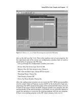
... microcontroller installed onto the board. If you have an ac
adapter for the EPIC programmer board, plug it into the board. If not, attach
two fresh 9-V batteries. Connect the “battery on” jumper to apply ... disconnect the printer, if one is connected, and attach
the EPIC programming board, using a 6-ft DB25 cable.
When you connect the EPIC programming board to the...
McGraw.Hill PIC Robotics A Beginners Guide to Robotics Projects Using the PIC Micro eBook-LiB Part 4 ppt
... command to communicate and output mes-
sages to the LCD display.
The PicBasic and PicBasic Pro compilers can send and receive serial
information at 300, 120 0, 24 00, and 9600 Bd. Data are sent as ... breadboard area.
gram, with the exception that we are only using one LED this time. The fol-
lowing are a small PicBasic program and PicBasic Pro program to blink an
LED on...
McGraw.Hill PIC Robotics A Beginners Guide to Robotics Projects Using the PIC Micro eBook-LiB Part 5 docx
... Location
16 8 4 2 1
RA0
RA1
RA2
RA3
RA4
Figure 6 .22 Diagram of port A registers.
69
78 Chapter Six
The PicBasic Pro has an additional command structure that can be used
with both the input and output ... could be a rock
Testing the PIC Microcontroller 81
(2) 22 -pF capacitors
(1) Solderless breadboard RadioShack PN# 27 6-175
(1) 0.1-F capacitor
RadioShack PN# 27 2-...
McGraw.Hill PIC Robotics A Beginners Guide to Robotics Projects Using the PIC Micro eBook-LiB Part 6 pps
... will also carry the light-gauge sheet metal and aluminum bar
materials needed to make the chassis.
I built the chassis out of (
1
8
-
1
2
-in) aluminum rectangle bar and 22 - to 24 -
gauge ... lamps on each tortoise shell. The robots
developed an interaction that to an observer appears as a kind of social behav-
ior. The robots danced around each other, at time...

McGraw.Hill PIC Robotics A Beginners Guide to Robotics Projects Using the PIC Micro eBook-LiB Part 7 pps
... also vary from one another and then are not as closely matched.
Once you have a pair of CdS cells to use, they need to be attached to the
robot. I soldered the CdS cells and capacitors to a ... first look at how the standard program functions.
Fudge Factor
The variable RV (range value) is the fudge factor. At the beginning of the pro-
gram the variable RV is ass...

McGraw.Hill PIC Robotics A Beginners Guide to Robotics Projects Using the PIC Micro eBook-LiB Part 8 ppt
... 9.9).
The second gearbox motor is secured to the other side in a similar manner.
Back wheels
The shaft diameter of the gearbox motor is a little too small to make a good
friction fit to the ... that matches
,
as best as one can match them,
in resistance.
Since the resistance values of the CdS cells can vary so greatly, it’s a good
idea to buy a few more t...

McGraw.Hill PIC Robotics A Beginners Guide to Robotics Projects Using the PIC Micro eBook-LiB Part 9 pps
...
Mounting the servomotors
The back servomotors are attached to the aluminum body using plastic 6- 32
machine screws and nuts. The reason I used plastic screws is that the plas-
4
Hexapod Walker ...
Pressure is applied to bend the aluminum bar at a 90° angle. It’s best to apply
pressure at the base of the aluminum bar close to the vise. This will bend the...

McGraw.Hill PIC Robotics A Beginners Guide to Robotics Projects Using the PIC Micro eBook-LiB Part 10 ppsx
... servomotor (see Fig.
12. 2), the bracket becomes a modular component that may be attached to oth-
er brackets and components. The bracket allows the top and bottom compo-
nents to swivel along the axis ... less than the interface board containing 10 relays. The advantage of the
relay board is that the miniature power relays have enough current capacity
to directly c...
Từ khóa:
- learning php data objects a beginners guide to php data objects pdf
- php this a beginners guide to learning object oriented php download
- a beginners guide to the study of religion pdf
- a beginners guide to the study of religion ebook
- a beginners guide to the study of religion herling
- php a beginners guide mcgraw hill professional
- php a beginners guide mcgraw hill
- beginners guide to embedded c programming using the pic microcontroller
- beginners guide to embedded c programming using the pic microcontroller pdf
- a practical guide to linux commands
- intellectual property and open source a practical guide to protecting code
- beginners guide to xhtml
- php a beginners guide
- a programmers guide to adonet in c
- beginners guide to ecommerce
- Báo cáo quy trình mua hàng CT CP Công Nghệ NPV
- Nghiên cứu sự hình thành lớp bảo vệ và khả năng chống ăn mòn của thép bền thời tiết trong điều kiện khí hậu nhiệt đới việt nam
- Giáo án Sinh học 11 bài 13: Thực hành phát hiện diệp lục và carôtenôit
- Giáo án Sinh học 11 bài 13: Thực hành phát hiện diệp lục và carôtenôit
- Giáo án Sinh học 11 bài 13: Thực hành phát hiện diệp lục và carôtenôit
- ĐỒ ÁN NGHIÊN CỨU CÔNG NGHỆ KẾT NỐI VÔ TUYẾN CỰ LY XA, CÔNG SUẤT THẤP LPWAN
- Quản lý hoạt động học tập của học sinh theo hướng phát triển kỹ năng học tập hợp tác tại các trường phổ thông dân tộc bán trú huyện ba chẽ, tỉnh quảng ninh
- Phối hợp giữa phòng văn hóa và thông tin với phòng giáo dục và đào tạo trong việc tuyên truyền, giáo dục, vận động xây dựng nông thôn mới huyện thanh thủy, tỉnh phú thọ
- Phát triển du lịch bền vững trên cơ sở bảo vệ môi trường tự nhiên vịnh hạ long
- Phát hiện xâm nhập dựa trên thuật toán k means
- Nghiên cứu về mô hình thống kê học sâu và ứng dụng trong nhận dạng chữ viết tay hạn chế
- Thơ nôm tứ tuyệt trào phúng hồ xuân hương
- Thiết kế và chế tạo mô hình biến tần (inverter) cho máy điều hòa không khí
- Tổ chức và hoạt động của Phòng Tư pháp từ thực tiễn tỉnh Phú Thọ (Luận văn thạc sĩ)
- BT Tieng anh 6 UNIT 2
- Tranh tụng tại phiên tòa hình sự sơ thẩm theo pháp luật tố tụng hình sự Việt Nam từ thực tiễn xét xử của các Tòa án quân sự Quân khu (Luận văn thạc sĩ)
- Giáo án Sinh học 11 bài 15: Tiêu hóa ở động vật
- Giáo án Sinh học 11 bài 15: Tiêu hóa ở động vật
- chuong 1 tong quan quan tri rui ro
- Giáo án Sinh học 11 bài 14: Thực hành phát hiện hô hấp ở thực vật