Where Am I-Sensors and methods for mobile robot positioning - Borenstein(2001) Part 15 docx

Tài liệu Where am I? Sensors and Methods for Mobile Robot Positioning ppt
... iron and nickel) and mumetal (iron, nickel,
Where am I?
Sensors and Methods for
Mobile Robot Positioning
by
J. Borenstein , H. R. Everett , and L. Feng
123
Contributing authors: S. W. Lee and ... code
Part I
Sensors for
Mobile Robot Positioning
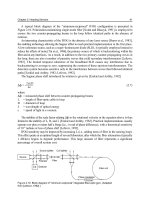
axis
n
co
n
cl
Waveguide
NA ' sin2
c
' n
2
co
&n
2
cl
2
1
Numerical aperture
Waveguide
axis
40 Part...

Where.Am.I-Sensors.and.methods.for.mobile.robot.positioning.-.Borenstein(2001) Part 2 ppsx
... Multi-Degree-of-Freedom Vehicles
Multi-degree-of-freedom (MDOF) vehicles have multiple
drive and steer motors. Different designs are possible. For
example, HERMIES-III, a sophisticated platform ... Futaba FP-G154 [FUTABA] is a low-
cost low-accuracy mechanical rate gyro
designed for use in radio-controlled model
helicopters and model airplanes. The Futaba
FP-G154 costs less than $150...
Where.Am.I-Sensors.and.methods.for.mobile.robot.positioning.-.Borenstein(2001) Part 3 pps
... the same for both the
Andrew 3ARG-A and the Hitachi OFG-3 gyros: 0.05 /s. If either gyro was installed on a robot with
a systematic error (e.g., due to unequal wheel diameters; see Sec. 5.1 for ... while model 3ARG-D ($1,100) has
an RS-232 output for connection to a com-
puter. Technical specifications for the
3ARG-D are given in Table 2.1. Specifica-
tions for the 3ARG-A are si...

Where.Am.I-Sensors.and.methods.for.mobile.robot.positioning.-.Borenstein(2001) Part 5 pptx
... Corp.)
Parameter E-220B/ 215 E-220B /150 E-220B/40 E-220B/26 Units
Range 10 - 61
4 - 24
20 - 152
8 - 60
61 - 610
24 - 240
61 - 914
24 - 360
cm
in
Beamwidth 10 10 35 (15) 35 (15)
Frequency 215 150 40 ... rate 150 100 25 20 Hz
Resolution 0.076
0.03
0.1
0.04
0.76
0.3
1
0.4
cm
in
Power 8 - 15 8 - 15 8 - 15 8 - 15 VDC
Weight 4 - 8 4...

Where.Am.I-Sensors.and.methods.for.mobile.robot.positioning.-.Borenstein(2001) Part 6 pot
... line
diode
Laser
Start
Stop
Peak
detector
Range
gate
Detector
Trigger
circuit
Threshold
detector
Ref
106 Part I Sensors for Mobile Robot Positioning
Figure 4.14:
Simplified block diagram of the
AutoSense II
time-of-flight 3-D ranging system. (Courtesy of
Schwartz Electro-Optics, Inc.)
Parameter ... in the
scene.
116 Part I Sensors for Mobile Robot Positioning
Parameter...

Where.Am.I-Sensors.and.methods.for.mobile.robot.positioning.-.Borenstein(2001) Part 7 doc
... 3 kilograms (6.75 lb), and
operates from 12 or 24 VDC with a nominal power
consumption of 20 W. An RS-232 digital output is
available.
X [mm]
-2 50
-2 00
-1 50
-1 00
-5 0
50
100
-5 0 50 100 150 200 ... compression circuit from in [Adams and Probert, 1995].
(Reproduced with permission from [Adams and Probert, 1995].)
138 Part II Systems and Methods for Mobile...

Where.Am.I-Sensors.and.methods.for.mobile.robot.positioning.-.Borenstein(2001) Part 8 pptx
... zero, and the gyros should ideally show ).
Barshan and Durrant-Whyte determined that the standard deviation, here used as a measure for the
152 Part II Systems and Methods for Mobile Robot Positioning
Triangulation
In ... [NAMCO,
1989]
= Vt - 45 (6.2)
b
where
= target angle
V = scan velocity (7,200 /s)
T = time between scan initiation and target
b
detection.
150...

Where.Am.I-Sensors.and.methods.for.mobile.robot.positioning.-.Borenstein(2001) Part 10 pot
... 0.7
B
(150 , -5 00) 5.7 ( 2-1 /4) 1.9
C
(1000, -5 00) 9.1 ( 3-1 /2) 5.3
D
(1800 ,-5 00) 55.8 (22) 5.9
E
(1800 ,-8 00) 63.2 (25) 6.8
Table 8.2: Hand-measured position error of the robot
at intermediate way-points ... was said to be 15 centimeters (6 in).
182 Part II Systems and Methods for Mobile Robot Positioning
Figure 7.10: The odor-laying/odor-sensing mobi...

Where.Am.I-Sensors.and.methods.for.mobile.robot.positioning.-.Borenstein(2001) Part 11 pps
... δθ
θ
camera camera camera
sang03.cdr, .wmf
210 Part II Systems and Methods for Mobile Robot Positioning
Figure 9.3:
a. Possible camera locations (circular arc) determined by two rays and corresponding ... positioning means finding position and orientation of a sensor
or a robot. Since the general framework of landmark-based and map-based positioning, as well as the
met...
Từ khóa:
- free download english dictionary with pronunciation and meaning for mobile
- tips tricks and tidbits for the robot experiment
- tools and methods for debugging formulas
- use properties and methods for attributes and operations essential to a type
- policies a timeline and methods for transition
- data sources and methods for estimation of mortality by cause age and sex
- patients and methods for uk analysis
- patients and methods for the denmark analysis
- skeletal muscle satellite cells background and methods for isolation and analysis in a primary culture system
- techniques and methods for implant surface characterization
- presence detection and methods for mitigation
- plan and methods for evaluating success of project activities and documenting potential impact against measurable short and mid term outcomes are suitable and feasible
- specification languages and methods for annotation based verification
- definitions and methods for its determination
- application security and methods for reducing insider computer fraud
- Báo cáo thực tập tại nhà thuốc tại Thành phố Hồ Chí Minh năm 2018
- Báo cáo quy trình mua hàng CT CP Công Nghệ NPV
- Nghiên cứu tổ chức pha chế, đánh giá chất lượng thuốc tiêm truyền trong điều kiện dã ngoại
- Một số giải pháp nâng cao chất lượng streaming thích ứng video trên nền giao thức HTTP
- Nghiên cứu tổ chức chạy tàu hàng cố định theo thời gian trên đường sắt việt nam
- đề thi thử THPTQG 2019 toán THPT chuyên thái bình lần 2 có lời giải
- Biện pháp quản lý hoạt động dạy hát xoan trong trường trung học cơ sở huyện lâm thao, phú thọ
- Giáo án Sinh học 11 bài 13: Thực hành phát hiện diệp lục và carôtenôit
- Giáo án Sinh học 11 bài 13: Thực hành phát hiện diệp lục và carôtenôit
- Giáo án Sinh học 11 bài 13: Thực hành phát hiện diệp lục và carôtenôit
- Giáo án Sinh học 11 bài 13: Thực hành phát hiện diệp lục và carôtenôit
- Giáo án Sinh học 11 bài 13: Thực hành phát hiện diệp lục và carôtenôit
- ĐỒ ÁN NGHIÊN CỨU CÔNG NGHỆ KẾT NỐI VÔ TUYẾN CỰ LY XA, CÔNG SUẤT THẤP LPWAN
- Phát triển du lịch bền vững trên cơ sở bảo vệ môi trường tự nhiên vịnh hạ long
- Nghiên cứu, xây dựng phần mềm smartscan và ứng dụng trong bảo vệ mạng máy tính chuyên dùng
- Thơ nôm tứ tuyệt trào phúng hồ xuân hương
- Sở hữu ruộng đất và kinh tế nông nghiệp châu ôn (lạng sơn) nửa đầu thế kỷ XIX
- BT Tieng anh 6 UNIT 2
- Tranh tụng tại phiên tòa hình sự sơ thẩm theo pháp luật tố tụng hình sự Việt Nam từ thực tiễn xét xử của các Tòa án quân sự Quân khu (Luận văn thạc sĩ)
- Giáo án Sinh học 11 bài 15: Tiêu hóa ở động vật