Gear Geometry and Applied Theory Episode 2 Part 10 doc

Gear Geometry and Applied Theory Episode 2 Part 10 doc
... left-hand worm and worm -gear, we have
R
o
=
p
ax
N
2
cos λ
(o)
1
2 sin
γ + λ
(o)
1
. (19.3 .10)
P1: JsY
CB6 72- 19 CB6 72/ Litvin CB6 72/ Litvin-v2.cls February 27 , 20 04 1 :28
19.5 Generation and Geometry ... d
sin α sin λ
p
(cos
2
α + sin
2
α sin
2
λ
p
)
0.5
(19.5 .20 )
where
d = r
p
−
s
p
2
cot α.
P1: JsY
CB6 72- 19 CB6 72/ Litvin CB6 72/ Litvin-v2.cls February...
Gear Geometry and Applied Theory Episode 2 Part 1 pot
... FHA/JTH
CB6 72- 10 CB6 72/ Litvin CB6 72/ Litvin-v2.cls February 27 , 20 04 0:19
10. 8 Contact Ratio 29 3
Thus,
l = KB
2
+ B
1
L − KL =
r
2
a1
−r
2
b1
1
2
+
r
2
a2
−r
2
b2
1
2
− E sin α (10. 8.5)
or
l ... that
w
a2
= 2r
a2
(q
2
− inv α
a2
) (11.3.3)
P1: FHA/JTH
CB6 72- 10 CB6 72/ Litvin CB6 72/ Litvin-v2.cls February 27 , 20 04 0:19
28 8 Spur Involute Gears...

Gear Geometry and Applied Theory Episode 2 Part 2 doc
... ( 12. 2.4)
Equations ( 12. 2.1), ( 12. 2.3), and ( 12. 2.4) yield
tan µ
1
=−
m
12
(φ
1
) ± 1
m
12
(φ
1
)
( 12. 2.5)
tan µ
2
=±
m
12
(φ
1
) ± 1
m
12
(φ
1
)
. ( 12. 2.6)
Here, m
12
= (∂/∂φ
1
)[m
12
(φ
1
)].
Function ... ratio function is
m
12
=
dφ
1
dφ
2
=
k
1
k
2
y
x
( 12. 2.8)
P1: GDZ/SPH P2: GDZ
CB6 72- 12 CB6 72/ Litvin CB6 72/ Litvin-v2.cls February 27 , 20 0...

Gear Geometry and Applied Theory Episode 2 Part 3 pot
... equation
r
t
(θ
2
,φ
2
) = M
t2
(φ
2
)r
2
(θ
2
), (13.6.5)
which yields
θ
2
≥ 90
◦
,φ
2
= 2( θ
2
− 90
◦
)
x
t
=−r
2
(φ
2
− sin φ
2
) +ρ
2
sin(θ
2
− φ
2
)
y
t
=−r
2
(1 −cos φ
2
) −ρ
2
cos(θ
2
− φ
2
).
(13.6.6)
Axis ... represented in S
2
by the equations
ρ
2
(θ
2
) = ρ
2
[sin θ
2
− cos θ
2
01]
T
( 12. B.1)
n
2
= [sin θ
2
− cos θ
2
0]
T
....

Gear Geometry and Applied Theory Episode 2 Part 4 pdf
... 14.3.3):
x
2
= r
b2
cos(θ
2
− η
2
) + u
2
cos λ
b2
sin(θ
2
− η
2
)
y
2
=−r
b2
sin(θ
2
− η
2
) + u
2
cos λ
b2
cos(θ
2
− η
2
)
z
2
= u
2
sin λ
b2
− p
2
θ
2
(14.3.15)
n
2
= [sin λ
b2
sin(θ
2
− η
2
) sin ... 14.3.3):
x
2
= r
b2
cos(θ
2
− η
2
) + u
2
cos λ
b2
sin(θ
2
− η
2
)
y
2
= r
b2
sin(θ
2
− η
2
) − u
2
cos λ
b2
cos(θ
2
− η
2
)
z
2...

Gear Geometry and Applied Theory Episode 2 Part 5 pptx
... cases
P1: GDZ/SPH P2: GDZ
CB6 72- 15 CB6 72/ Litvin CB6 72/ Litvin-v2.cls February 27 , 20 04 0:44
15 .2 Axodes of Helical Gears and Rack-Cutters 409
Figure 15 .2. 2: Normal sections of pinion and gear rack-cutters: ... M
ba
[a
c
u
2
c
u
c
01]
T
(15 .2. 7)
P1: GDZ/SPH P2: GDZ
CB6 72- 15 CB6 72/ Litvin CB6 72/ Litvin-v2.cls February 27 , 20 04 0:44
422 Modified Involute Gears
Figu...

Gear Geometry and Applied Theory Episode 2 Part 6 ppsx
... 3D-space.
Worm
Helical gear
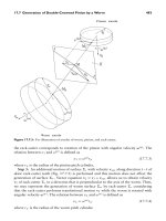
Figure 16.1 .2: Gear drive formed by a worm and a helical
gear.
P1: GDZ/SPH P2: GDZ
CB6 72- 15 CB6 72/ Litvin CB6 72/ Litvin-v2.cls February 27 , 20 04 0:44
1
2
3
Figure 15.9.1: Whole gear drive ... r
p2
π
N
2
= 8. 522 1 mm.
Radii of addendum and dedendum cylinders:
r
pa1
= r
p1
+ m
pn
= 39. 524 5 mm
r
pa2
= r
p2
+ m
pn
= 82. 6678 mm
r
pd 1
= r
p1...
Gear Geometry and Applied Theory Episode 2 Part 7 pps
... λ
o2
(16.B.8)
sin
2
γ
o
cos
2
α
on
= cos
2
λ
b1
sin
2
λ
o2
± 2 cos λ
b1
cos λ
b2
sin λ
o1
sin λ
o2
+ cos
2
λ
b2
sin
2
λ
o1
= cos
2
λ
b1
± 2 cos λ
b1
cos λ
b2
sin λ
o1
sin λ
o2
+ cos
2
λ
b2
−
2 ... Pressure
-8.935e+01
+2. 500e+01
+9.553e+01
+1.661e+ 02
+2. 366e+ 02
+3.071e+ 02
+3.776e+ 02
+4.482e+ 02
+5.187e+ 02
+5.892e+ 02
+6.598e+ 02
+7.303e+ 02
+8.008e+ 02
+...
Gear Geometry and Applied Theory Episode 2 Part 8 pps
... Section 3.4)
cot γ
1
=
m
12
+ cos γ
sin γ
, cot γ
2
=
m
21
+ cos γ
sin γ
=
1 + m
12
cos γ
m
12
sin γ
(18 .2. 2)
P1: JXR
CB6 72- 18 CB6 72/ Litvin CB6 72/ Litvin-v2.cls February 27 , 20 04 1:5
18.1 Introduction ... ”“s” and “1, ” and “1” and
2 are considered. Angle γ
s
that is formed between the shaper axis and IA
s2
is
P1: JXR
CB6 72- 18 CB6 72/ Litvin CB6 72/ Litvin-v2.cl...
Gear Geometry and Applied Theory Episode 2 Part 9 pps
... JsY
CB6 72- 19 CB6 72/ Litvin CB6 72/ Litvin-v2.cls February 27 , 20 04 1 :28
19 .2 Pitch Surfaces and Gear Ratio 551
Figure 19 .2. 2: Velocity polygon for right-
hand worm -gear drive.
Figure 19 .2. 3: Operating ... pitch cylinders
for left-hand worm -gear drive.
P1: JsY
CB6 72- 19 CB6 72/ Litvin CB6 72/ Litvin-v2.cls February 27 , 20 04 1 :28
19 .2 Pitch Surfaces and Gear...
Từ khóa:
- oxford english for careers oil and gas 2 part 1
- sql and relational theory
- strain and the theory of elasticity
- kĩ thuật chế tạo máy phần 2 part 1đồ án
- literary response and analysis from the odyssey part one
- unit 13 films and cinema writing task 2
- Nghiên cứu sự biến đổi một số cytokin ở bệnh nhân xơ cứng bì hệ thống
- Báo cáo quy trình mua hàng CT CP Công Nghệ NPV
- chuyên đề điện xoay chiều theo dạng
- Nghiên cứu tổ chức pha chế, đánh giá chất lượng thuốc tiêm truyền trong điều kiện dã ngoại
- đề thi thử THPTQG 2019 toán THPT chuyên thái bình lần 2 có lời giải
- ĐỒ ÁN NGHIÊN CỨU CÔNG NGHỆ KẾT NỐI VÔ TUYẾN CỰ LY XA, CÔNG SUẤT THẤP LPWAN
- Quản lý hoạt động học tập của học sinh theo hướng phát triển kỹ năng học tập hợp tác tại các trường phổ thông dân tộc bán trú huyện ba chẽ, tỉnh quảng ninh
- Phối hợp giữa phòng văn hóa và thông tin với phòng giáo dục và đào tạo trong việc tuyên truyền, giáo dục, vận động xây dựng nông thôn mới huyện thanh thủy, tỉnh phú thọ
- Phát triển du lịch bền vững trên cơ sở bảo vệ môi trường tự nhiên vịnh hạ long
- Nghiên cứu khả năng đo năng lượng điện bằng hệ thu thập dữ liệu 16 kênh DEWE 5000
- Định tội danh từ thực tiễn huyện Cần Giuộc, tỉnh Long An (Luận văn thạc sĩ)
- Thơ nôm tứ tuyệt trào phúng hồ xuân hương
- Kiểm sát việc giải quyết tố giác, tin báo về tội phạm và kiến nghị khởi tố theo pháp luật tố tụng hình sự Việt Nam từ thực tiễn tỉnh Bình Định (Luận văn thạc sĩ)
- Quản lý nợ xấu tại Agribank chi nhánh huyện Phù Yên, tỉnh Sơn La (Luận văn thạc sĩ)
- Tăng trưởng tín dụng hộ sản xuất nông nghiệp tại Ngân hàng Nông nghiệp và Phát triển nông thôn Việt Nam chi nhánh tỉnh Bắc Giang (Luận văn thạc sĩ)
- Tranh tụng tại phiên tòa hình sự sơ thẩm theo pháp luật tố tụng hình sự Việt Nam từ thực tiễn xét xử của các Tòa án quân sự Quân khu (Luận văn thạc sĩ)
- Giáo án Sinh học 11 bài 15: Tiêu hóa ở động vật
- Nguyên tắc phân hóa trách nhiệm hình sự đối với người dưới 18 tuổi phạm tội trong pháp luật hình sự Việt Nam (Luận văn thạc sĩ)
- Giáo án Sinh học 11 bài 14: Thực hành phát hiện hô hấp ở thực vật
- Giáo án Sinh học 11 bài 14: Thực hành phát hiện hô hấp ở thực vật