the induction machine handbook chuong (9)
the induction machine handbook chuong (9)
... obtain their real values. On the other hand,
Equations (9.35) – (9.36) lead to the equivalent circuit in Figure 9.12.
Once the layer currents I
1
, … I
n
are known, the total losses in the bar ...
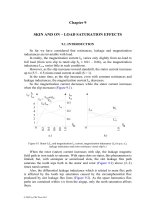
9.4. SKIN EFFECT IN THE END RINGS VIA THE MULTILAYER
APPROACH
As the end rings are placed in air, although rather close to the motor
laminated stack, the skin effect in...
the induction machine handbook chuong (1)
... and testing for induction
machines
• Integral induction motors: induction motors with the PWM converter
integrated into one piece
1.3. INDUCTION MACHINES IN APPLICATIONS
Induction motors ... closed)
windings of the rotor. The interaction between the stator produced field and the
rotor induced currents produces torque and thus operates the induction motor.
As...
the induction machine handbook chuong (2)
... conductors on the part of the machine not
connected to the grid (the rotor, or the mover in general), - the secondary. If the
windings on the secondary (rotor) are closed, a.c. currents occur in the ... phase. In both cases the winding
arrangement on the part of the machine the primary–connected to the grid (the
stator in general) should produce a traveling f...
the induction machine handbook chuong (3)
... this
combination.
The insulation of the coil conductors (turns) is applied before inserting the
coils in slots. The coils are vacuum also impregnated outside the machine. The
slot insulation ... ………
The connections between the coils of a phase and the leads to the terminal
box have to be insulated. Also the binding cord used to tie down endwindings to
r...
the induction machine handbook chuong (4)
... and the other side in the second layer. They are
connected observing the inward (A, B, C) and outward (A’, B’, C’) directions of
currents in their sides.
Connecting the coils per phase
The ... Having two current paths, the current in the coils is half the current at the
terminals. Consequently, the wire gauge of conductors in the coils is smaller and
thus the c...

the induction machine handbook chuong (5)
... calculated for the fundamental airgap flux density.
This information prepares the ground to define the parameters of the equivalent
circuit of the induction machine, that is, for the computation ... r
m4
, (for the stator)
and r
m2
(for the rotor). Assuming that the radial magnetic field H is constant
along the circles r
m2
and r
m4
, the flux linkage equivalenc...

the induction machine handbook chuong (6)
...
The airgap flux does not reach the other slotted structure (Figure 6.10a)
while the zig-zag flux “snakes” out through the teeth around slot openings.
In general, they may be treated together ...
rotor phases. In reality the flux in the rotor varies at Sf
1
frequency, while in the
stator at f
1
frequency. The amplitude is the same and, with respect to each other,
th...

the induction machine handbook chuong (7)
... addition to the emf, there is only the stator resistance and leakage
inductance voltage drop.
Finally, as there is current (mmf) in the rotor, the emf E
1
is produced
concurrently by the two ... constitute the IM equations per phase reduced to
the stator for the rotor circuit.
Notice that in these equations there is only one frequency, the stator
frequency ω
1
, whic...

the induction machine handbook chuong (8)
... constant under steady state and the machine behaves like a
synchronous machine with the torque dependent on the power angle δ (S = f
2
/f
1
= ct).
On the other hand, the frequency f
2
may be varied ... when the load torque decreases, to reduce the flux level in the machine
and thus reduce the core losses and increase the power factor and efficiency
while stato...

the induction machine handbook chuong (10)
... order is a
multiple of the number of slots (10.12). The stator (rotor) mmfs may produce
harmonics of the same order either as sourced in the mmf or from the interaction
with the first airgap magnetic ...
The saturation coefficient K
st
in (10.40) refers to the teeth zone only as the
harmonics wavelength is smaller than that of the fundamental and therefore the
fl...
Từ khóa:
- phan phoi chuong trinh mon the duc 6 7 8 9
- câu 9 nội dung giáo dục thường xuyên được thể hiện trong các chương trình nào sau đây
- 1 cm2 and petioles 1 cm long from tissue cultured plantlets were used as explants for callus induction the explants were cultured in 90 mm petri dishes containing 25 ml of basal media supplemented with 4 44 µm ba an
- the wizard and the war machine
- the recording engineers handbook
- the electrical engineering handbook
- chương 9 trang bị phụ trong lò hơi
- giáo trình cung cấp điện chương 9
- giáo trình công nghệ chế tạo máy chương 9
- the natural remedy handbook
- the self improvement handbook
- rèn nghị lực để lập thân chương 9
- chương 9công cụ interactive blend tool
- lò hơi chương 9
- các ưu thế vượt trội của iso 9000
- Nghiên cứu sự biến đổi một số cytokin ở bệnh nhân xơ cứng bì hệ thống
- Báo cáo quy trình mua hàng CT CP Công Nghệ NPV
- Nghiên cứu tổ chức pha chế, đánh giá chất lượng thuốc tiêm truyền trong điều kiện dã ngoại
- đề thi thử THPTQG 2019 toán THPT chuyên thái bình lần 2 có lời giải
- Giáo án Sinh học 11 bài 13: Thực hành phát hiện diệp lục và carôtenôit
- ĐỒ ÁN NGHIÊN CỨU CÔNG NGHỆ KẾT NỐI VÔ TUYẾN CỰ LY XA, CÔNG SUẤT THẤP LPWAN
- Phát triển mạng lưới kinh doanh nước sạch tại công ty TNHH một thành viên kinh doanh nước sạch quảng ninh
- Trả hồ sơ điều tra bổ sung đối với các tội xâm phạm sở hữu có tính chất chiếm đoạt theo pháp luật Tố tụng hình sự Việt Nam từ thực tiễn thành phố Hồ Chí Minh (Luận văn thạc sĩ)
- Phát triển du lịch bền vững trên cơ sở bảo vệ môi trường tự nhiên vịnh hạ long
- Nghiên cứu, xây dựng phần mềm smartscan và ứng dụng trong bảo vệ mạng máy tính chuyên dùng
- Nghiên cứu về mô hình thống kê học sâu và ứng dụng trong nhận dạng chữ viết tay hạn chế
- Nghiên cứu tổng hợp các oxit hỗn hợp kích thƣớc nanomet ce 0 75 zr0 25o2 , ce 0 5 zr0 5o2 và khảo sát hoạt tính quang xúc tác của chúng
- Định tội danh từ thực tiễn huyện Cần Giuộc, tỉnh Long An (Luận văn thạc sĩ)
- Thiết kế và chế tạo mô hình biến tần (inverter) cho máy điều hòa không khí
- Kiểm sát việc giải quyết tố giác, tin báo về tội phạm và kiến nghị khởi tố theo pháp luật tố tụng hình sự Việt Nam từ thực tiễn tỉnh Bình Định (Luận văn thạc sĩ)
- Tăng trưởng tín dụng hộ sản xuất nông nghiệp tại Ngân hàng Nông nghiệp và Phát triển nông thôn Việt Nam chi nhánh tỉnh Bắc Giang (Luận văn thạc sĩ)
- Giáo án Sinh học 11 bài 15: Tiêu hóa ở động vật
- chuong 1 tong quan quan tri rui ro
- Giáo án Sinh học 11 bài 14: Thực hành phát hiện hô hấp ở thực vật
- Giáo án Sinh học 11 bài 14: Thực hành phát hiện hô hấp ở thực vật